Motivation
This is the Eurorack version of my NGF Moog Ladder Filter. I have brought out the 6dB, 12dB, 18dB and 24dB poles. Gain loss is corrected when turning up the emphasis/feedback. As a side effect off the gain corrections I got the emphasis voltage controlled as well. The exponential circuit is temperature compensated with KTY81-110. If the 12dB output is patched back to input 2 the filter can serve as a sine oscillator.
Specs and features
- Two inputs for easy mixing
- 6dB, 12dB, 18dB, 24dB output
- Gain loss compensation when emphasis is turned up
- Temperature compensation with KTY81-110
- Voltage controlled emphasis
- Usable as sine oscillator
- Runs on +/-12V and +/-15V (with minor resistor value changes for best performance)
- Power consumption around 40mA negative rail, 50mA positive rail
Implementation
Schematic

24dB Ladder Filter schematic: Main board

24dB Ladder Filter schematic: Control board
Description:
This is a classical Moog Ladder design implementation, nothing special to say about. All poles are brought out with instrumentation amplifiers. The voltage controlled emphasis is realized with means of one half LM13700 OTA (IC1OTA1). The control voltage for the emphasis is used to control the gain of four OTA (IC6OTA2, IC6OTA1, IC9OTA2, IC9OTA1) as well, one for each pole. The outputs of this OTA's are added to the instrumentation amplifiers for each pole to compensate for the gain loss with high emphasis. The added amount is adjustable by changing one resistor (R28, R47, R66, R69). Higher values means higher gain. The temperature compensation for the expo-converter is realized with KTY81-110. This is not realy needed for a filter but a nice additional feature if you use the filter as sine VCO. If not wanted it is easily replaced with a 1k resistor.
Screenshots
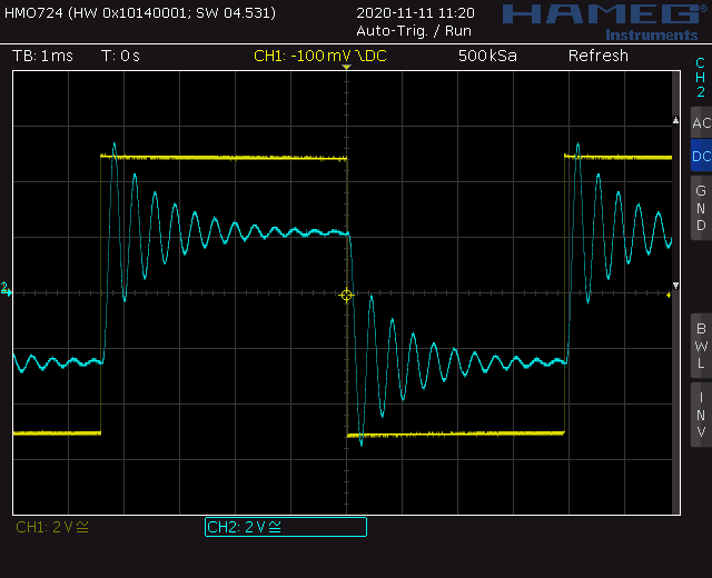
24dB Ladder Filter schematic: Screenshot high Q1
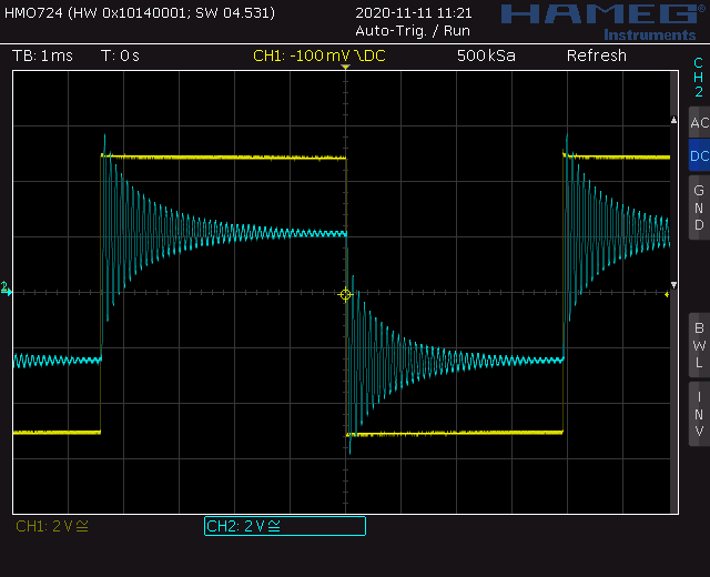
24dB Ladder Filter schematic: Screenshot high Q2
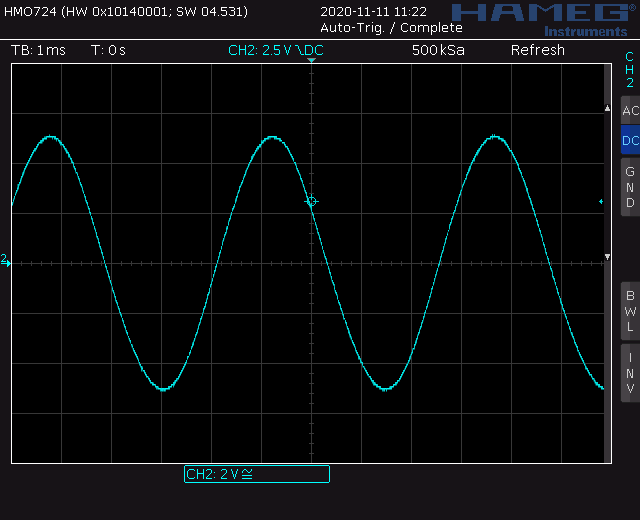
24dB Ladder Filter schematic: Screenshot sine out
Calibration
- OTA DC offset
- Set all potentiometers to zero.
- Measure the output at M_1 (M_2, M_3, M_4, M_5)
- Adjust trimmer TR_2 (TR_3, TR_4, TR_5, TR_1) to zero Volt (on main PCB).
- Turn the Q-Pot form zero to max and monitor the voltages at M_1, M_2, ... with the oscilloscope. They should be minimized. If not correct the trimmers until you reach the minimum. It might differ from OTA to OTA.
- Initial frequency
- Apply a sine with 10Vpp and the lowest frequency you want to filter to the input (Most common 20..40Hz).
- Close the Cut off pot completely. No feedback.
- Adjust Trimmer TR_2 (control PCB) for zero output with a scope.
- I use the 12dB output here. Which means you'll still have some signal bleed through at the 6dB output. If you don't like this use the 6dB output here.
- Feedback strength
- Apply a signal to the input. 100Hz square is a good start.
- Turn the feedback potentiometer to maximum.
- Adjust TR_1 (control PCB) to the amount you like. Try different signals.
- V/Octave
- Connect the 12dB output to input 2. No external signal in input 1.
- Turn input2-, cut-off- and feedback potentiometer to 3/4.
- You should see a sine at the 24dB output. If not increase the pot-settings.
- Adjust output volume with input2 pot to 10Vpp
- Turn the frequency down to around 100Hz with cut-off potentiometer
- Apply the control voltage to the V/Oct input (Keyboard, precision voltage source).
- Doubling the voltage should double the frequency. Adjust TR1 (control PCB) until it works.
Building hints
- The LM13700 differ in quality from part to part. You might want to select the IC for lowest DC output swing.
- Match transistors Q13 with Q14, Q11 with Q12, Q1 with Q2
Special parts
- None
Download
Ladder 24dB main board documentation downloadLadder 24dB main board Gerber files download
Ladder 24dB control board documentation download
Ladder 24dB control board Gerber files download
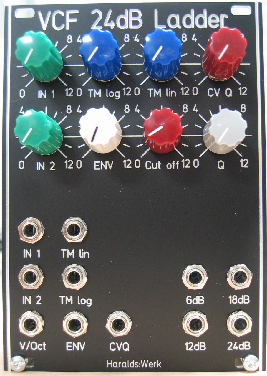
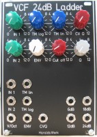
Ladder 24dB: Front view
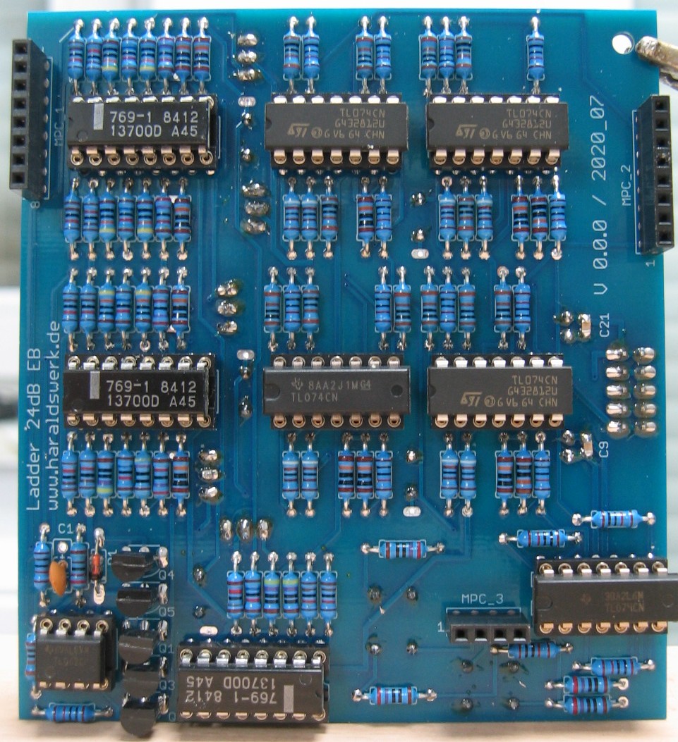
Ladder 24dB: Populated control PCB
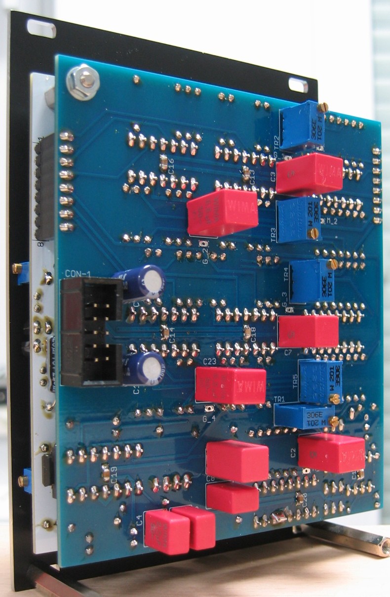
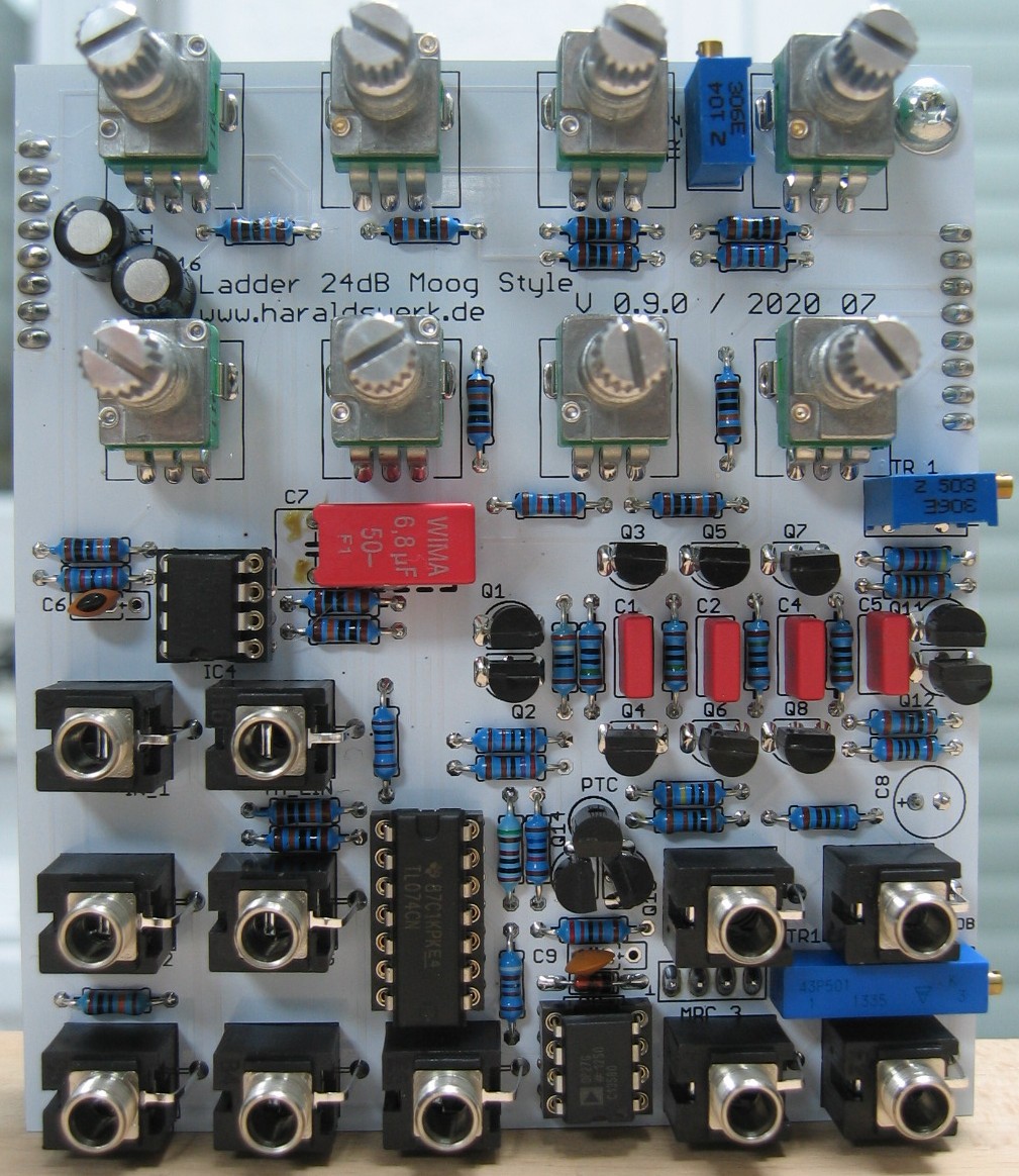
Ladder 24dB: Populated main PCB front view
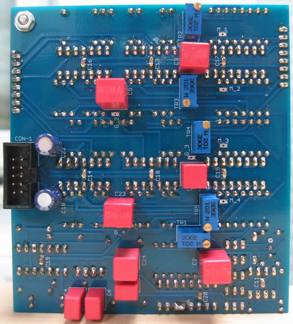
Ladder 24dB: Populated main PCB back view
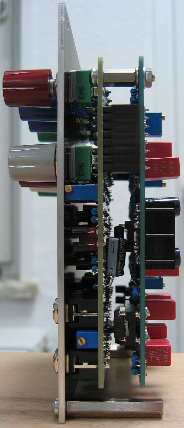
Ladder 24dB: Side view