Motivation
Why another Moog Ladder Filter? There are many decent implementations out there in the SDIY domain. Any reasons beside the joy of making something yourself? Well, I wanted to have some features that are not found in this combination elsewhere. First of all I wanted to get rid of loosing gain when the emphasis / feedback is turned up. And I wanted to bring all filter poles out. This means 6dB, 12dB, 18dB and 24dB outputs. As a side effect off the gain corrections I got the emphasis voltage controlled as well. The feedback loop can be opened so you can bring in some filtering or what ever you want in the feedback loop. The exponential circuit can be stuffed with discrete transistors or LM394 as well. And this circuit is temperature compensated with KTY81-110.
Specs and features
- 24dB Moog Ladder LPF
- 6db, 12dB and 18dB brought out to additional board
- Gain loss compensation when emphasis is turned up. Adjustable
- Temperature compensation with KTY81-110 (optional)
- Can be stuffed with ordinary (hand matched) transistors or LM394
- Voltage controlled emphasis
- Connector in the feedback path to ad special sound possibilities
- Log and lin timbre modulation
- Schematic
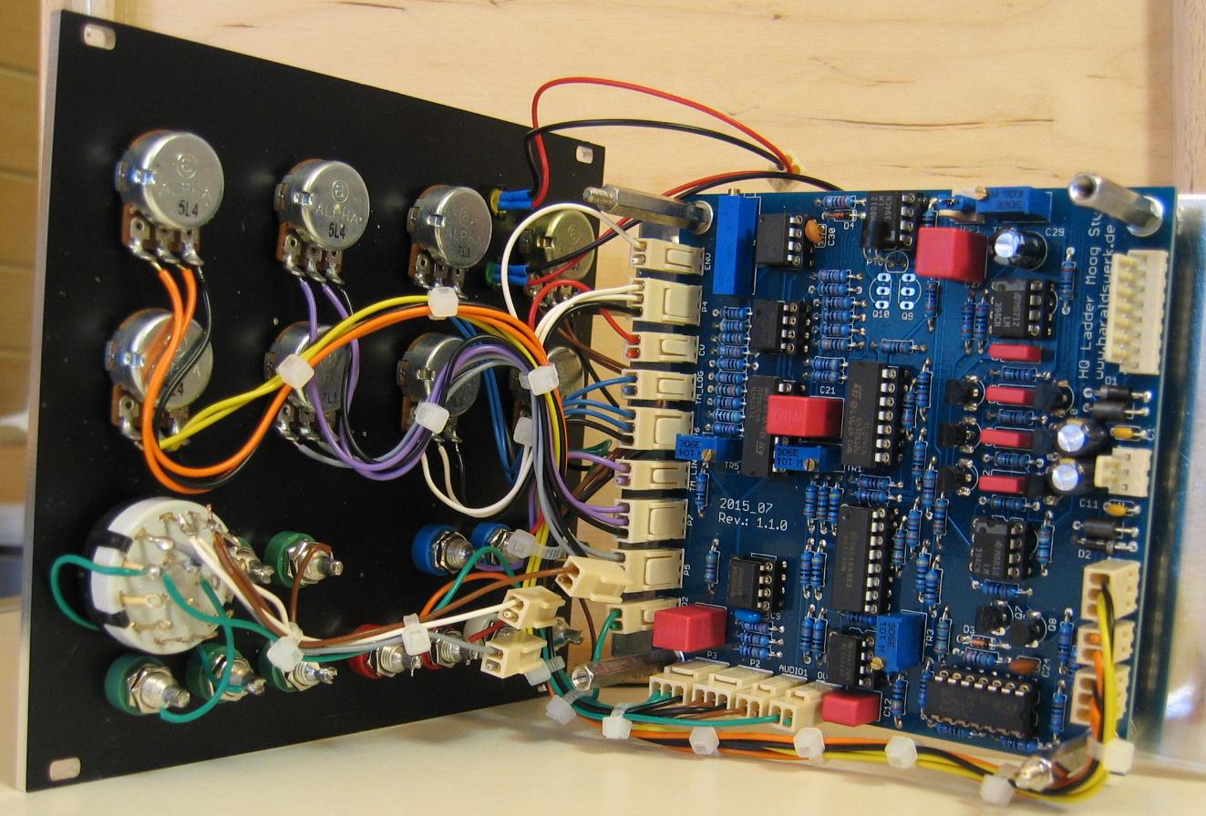
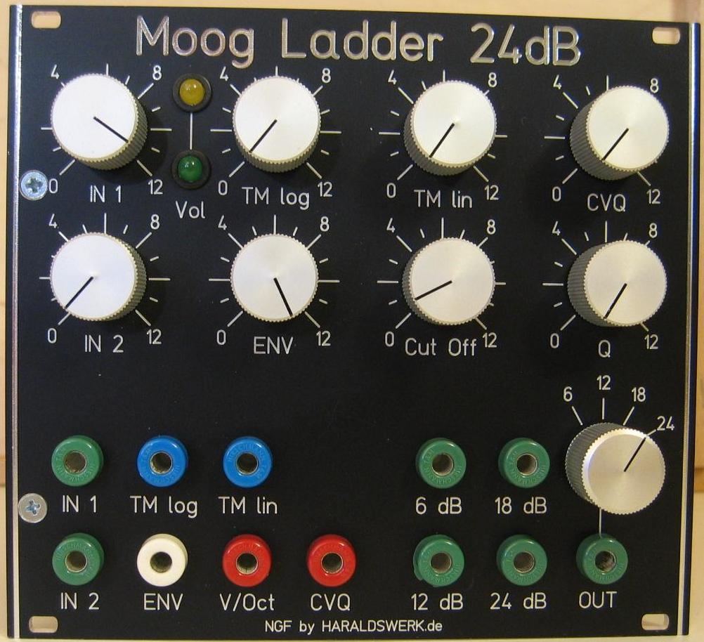
- Pictures
- Works on PSU with +12V/-12V or +15V/-15V as well
Implementation
Schematic
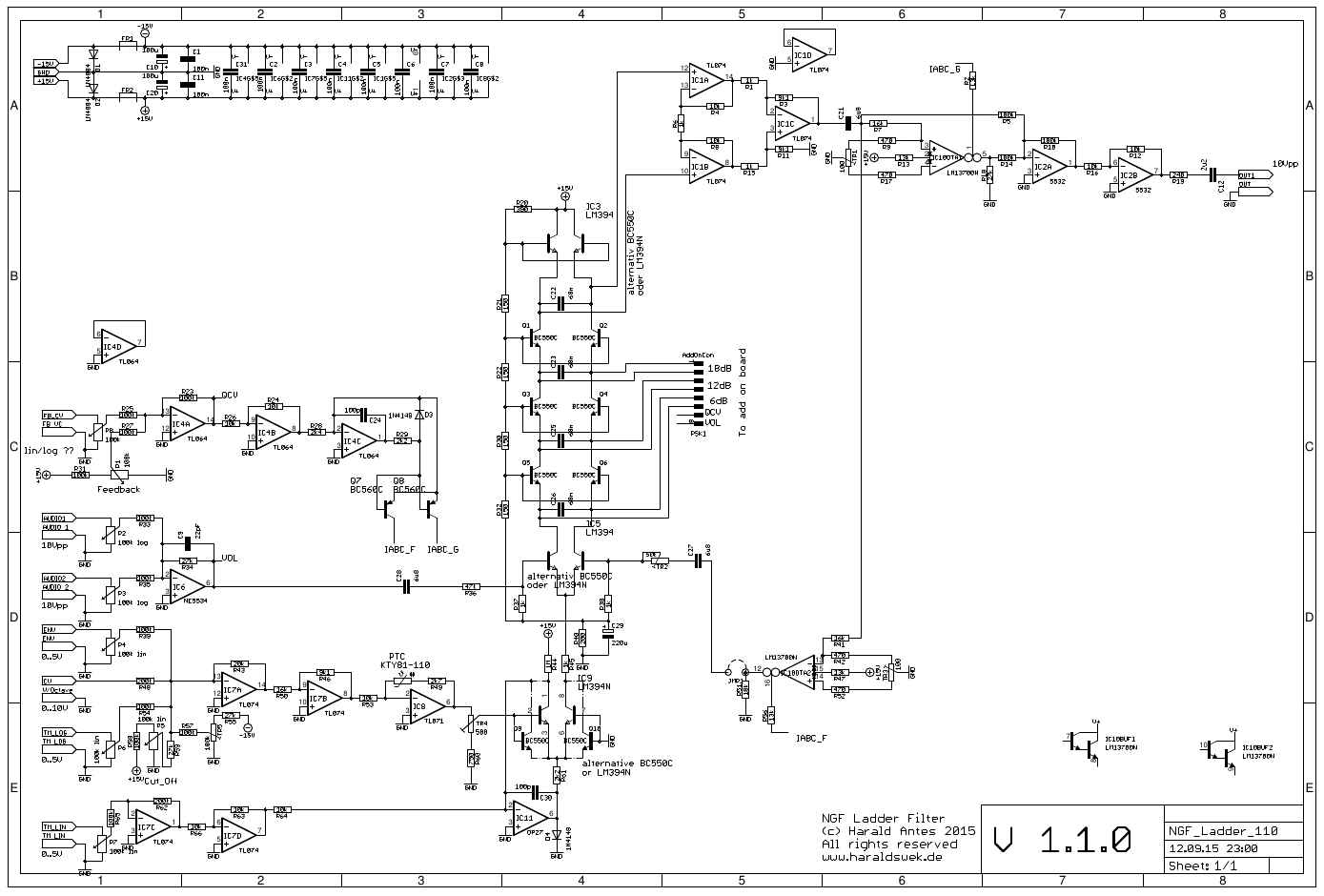
Description:
This is a classical Moog Ladder design implementation, nothing special to say about. The voltage controlled emphasis is realized with means of one half LM13700 OTA (IC10OTA2). The control voltage for the emphasis is used to control the gain of the second half LM13700 OTA (IC10OTA1) as well. The output of this OTA is added to the ladder output to compensate for the gain loss with high emphasis. The added amount is adjustable by changing one resistor. The temperature compensation for the expo-converter is realized with KTY81-110. This is not realy needed for a filter but a nice additional feature. If not wanted it is easily replaced with a 1k resistor.
TopCalibration
- OTA DC offset: Ground the input of the OTA, where C21 and R7/R41 met. Set the feedback potentiometer to maximum. Measure the output voltage at pin5 of IC10 (LM13700). Adjust TR1 to zero volts. Measure the output voltage at pin12 of IC10 (LM13700). Adjust TR3 to zero volts. Remove ground.
- Initial frequency: Apply a sine with 10Vpp and the lowest frequency you want to filter to the input (Most common 20..40Hz). Close the Cut off pot completely. No feedback. Adjust Trimmer TR5 for zero output with a scope.
- V/Octave: Apply a sine 200Hz 10Vpp to the input. Set CV to ground. Adjust Cut Off potentiometer for 4Vpp. Apply 1V DC to the CV input. The output voltage should double. Adjust TR4 until it fits. Repeat this step as often as necessary. Test: Double the input frequency to 400Hz. The output signal should drop to half.
- Feedback strength: Apply a signal to the input. Turn the feedback potentiometer to maximum. Adjust TR2 to the amount you like. Try different signals.
- Gain loss compensation: Choose R18 to your needs. 30k is a good start. Or replace R18 with a trimmer or potentiometer.
Special parts
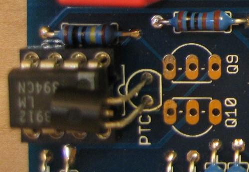
You can easily replace the LM394 with handmatched transistors. Match Q9 with Q10 and replace IC3 LM394 and IC5 LM394 with a matched pair. I use hand matched BC550C all the time with no loss in quality.
The temeperature compensation for the expo-converter is realized with KTY81-110. This is not realy needed for a filter but a nice additional feature. If not wanted it is easily replaced with a 1k resistor.
12V Operation
The filter works at 12V as well as with 15V. However the performance at 12V can be optimized by changing a few resistors.
- R47 and R13 from 13k to 11k (Diode bias current for LM13700).
- R56 and R2 from 13k to 10k (I_abc for LM13700).
Gain loss compensation at high emphasis
Nearly all filters suffer from gain loss when the emphasis / feedback is turned up. The technique used here could be applied to nearly all filter with an OpAmp output stage.
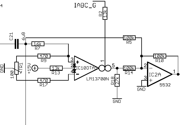
NGF Moog Ladder filter schematic detail
The LM13700 OTA is turned on when the control voltage for the feedback rises. Higher voltage means higher feedback and higher gain for the OTA. The output signal of the OTA is then added to the output signal from the instrumentation amplifier of the Moog Ladder with IC2A. The gain is determined by R18. You can compensate for the gain loss up to 100% (and more). But be careful. You need some headroom for the signal in your system. Check the pictures.
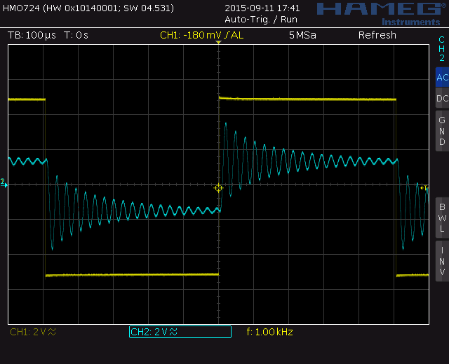
Output NGF Moog Ladder filter: No gain loss compensation
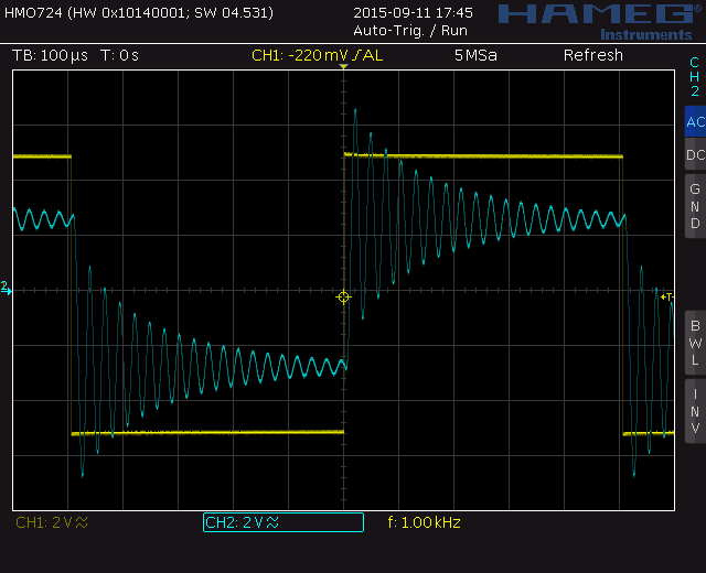
Output NGF Moog Ladder filter: Gain loss compensation R18=30k
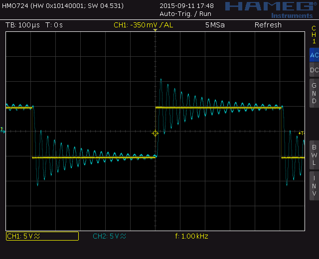
Output NGF Moog Ladder filter: 100% gain loss compensation R18=200k
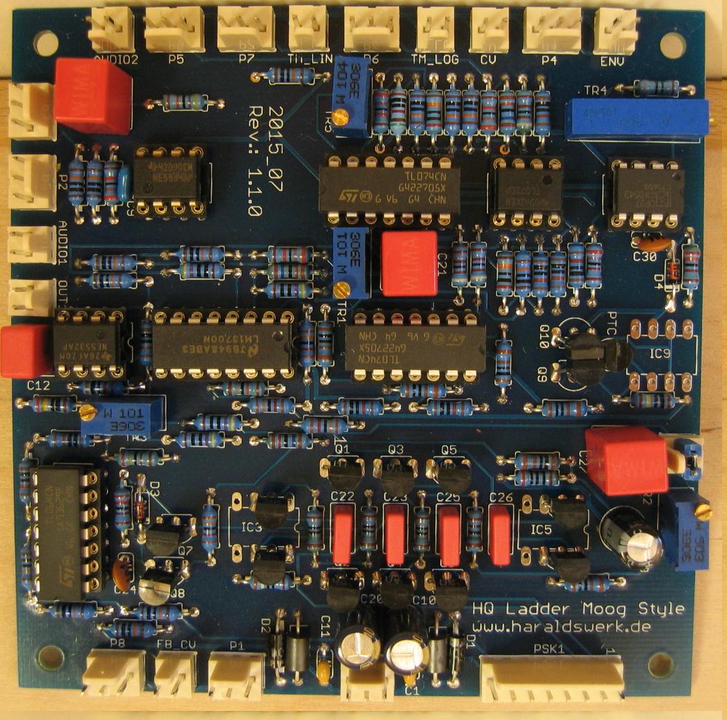
NGF Moog Ladder filter with BC550C
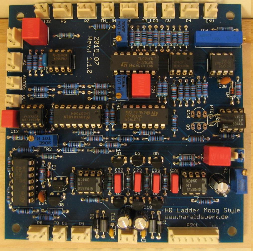
NGF Moog Ladder filter with LM394
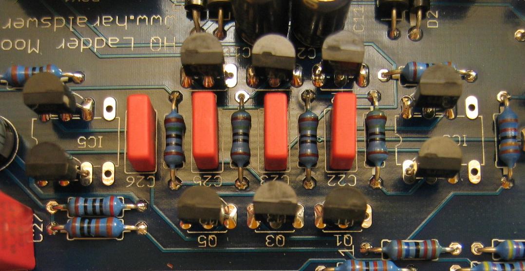
NGF Moog Ladder filter detail with BC550C
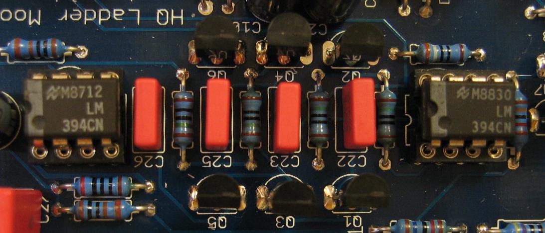
NGF Moog Ladder filter detail with LM394
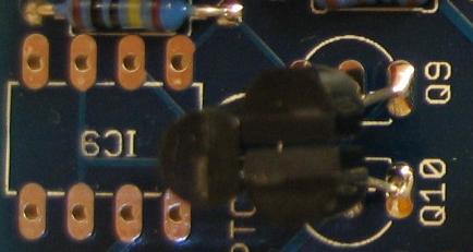
NGF Moog Ladder filter temperature compensation with KTY81-110 and BC550C
NGF Moog Ladder filter temperature compensation with KTY81-110 and LM394