Motivation
This is a 24dB lowpass / highpass with gain loss compensation for high Q. This one is basically derived from my 24dB VCF LP/HP which i build for my Next Generation Formant Elektor project. I just added the compensation circuitry from my Moog Ladder filter to compensate for the volume loss when Q is turned up. I have brought out all 4 filter stage outputs. Depending on your wiring you can use a switch to select between the outputs or/and bring all outputs out in parallel. The LP/HP switching is done with electronic switches on the PCB to avoid the problems (hum, noise...) of the wiring with a mechanical switch.
Specs and features
- 24dB voltage controlled low pass and high pass filter
- Switchable output 6dB, 12dB, 18dB, 24dB
- Volume loss compensation with high Q
- 10Vpp signal level
- Voltage controllable Q
- Voltage controlled lin and log timbre modulation
- Positive and negative ENV control with sign changer
- Runs on +/-15V and +/-12V (with minor resistor changes)
- Power consumption below 60 mA each rail
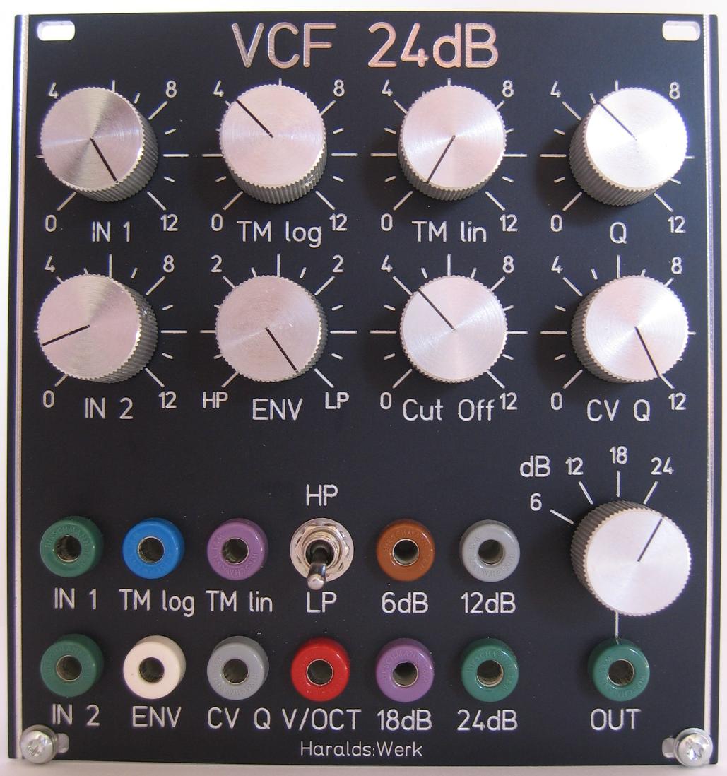
- Schematic 24dB VCF
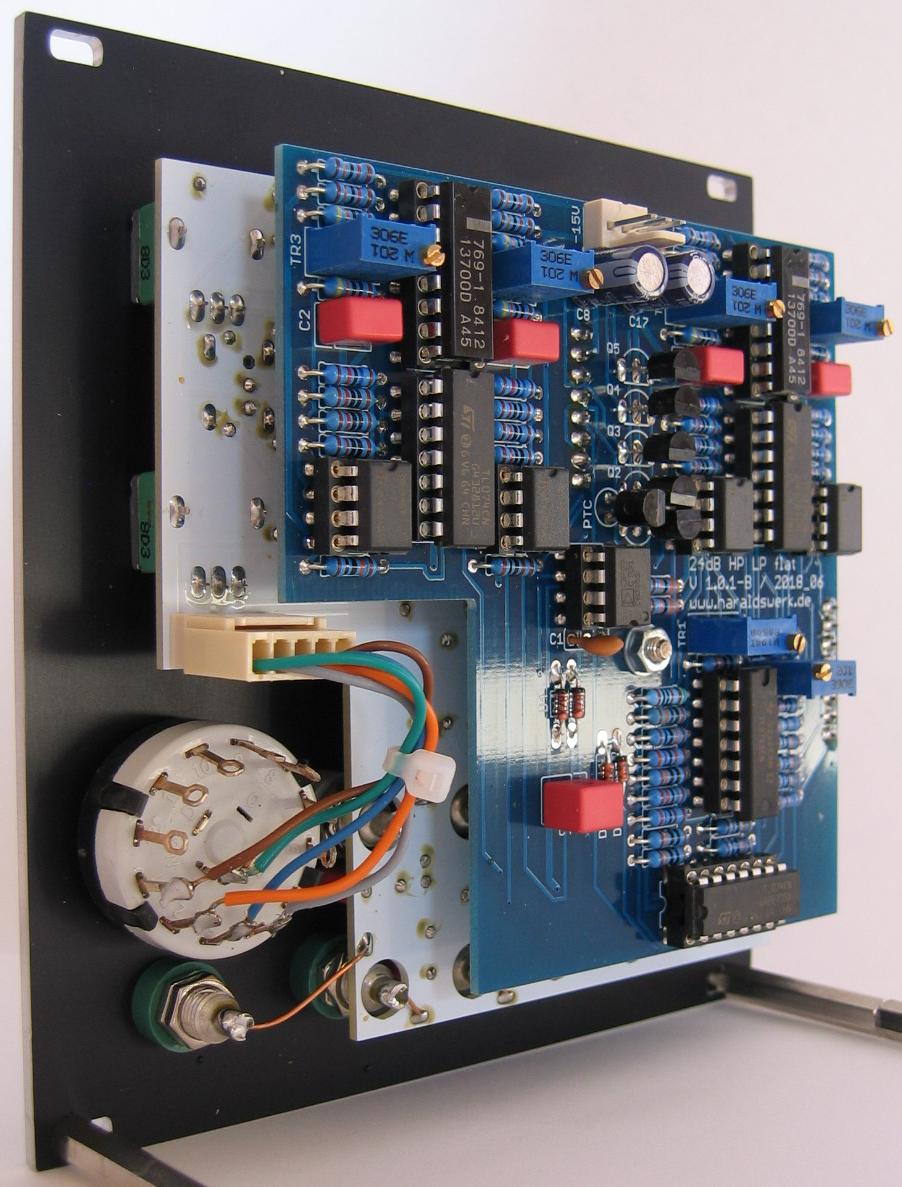
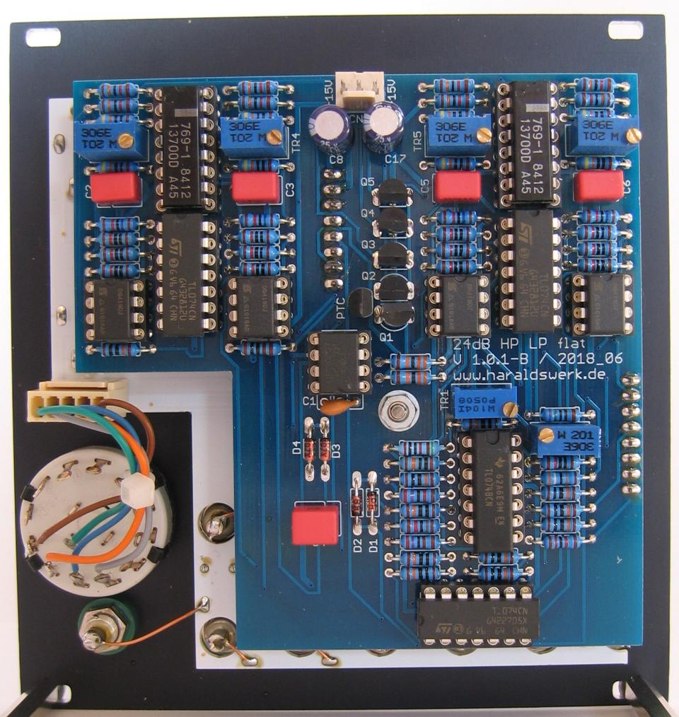
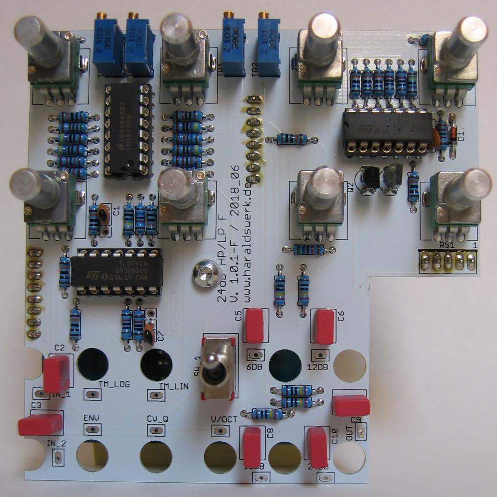
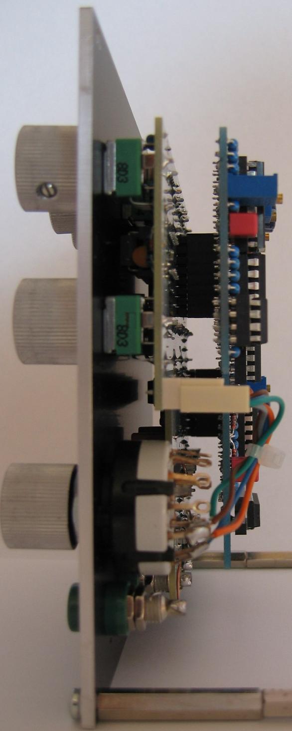
- Pictures
- Download docs
Implementation
Schematic
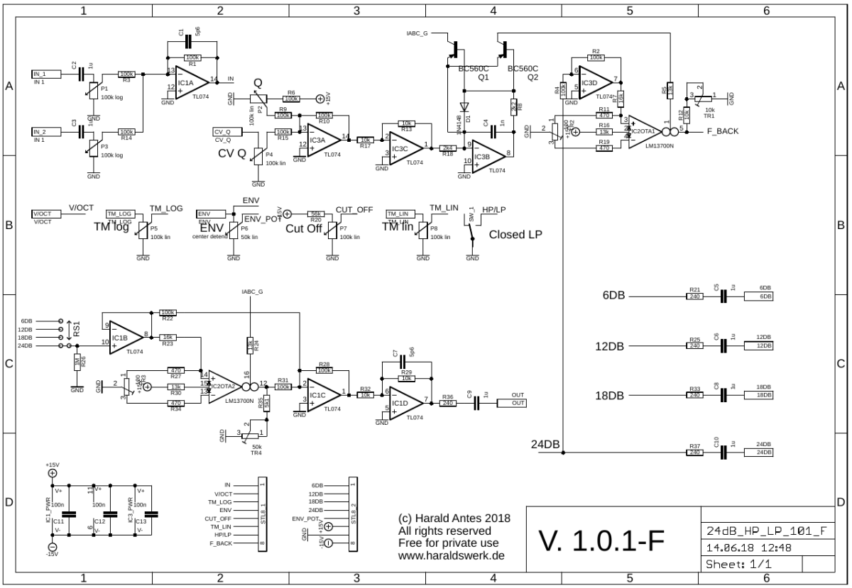
24dB VCF LP/HP schematic front PCB
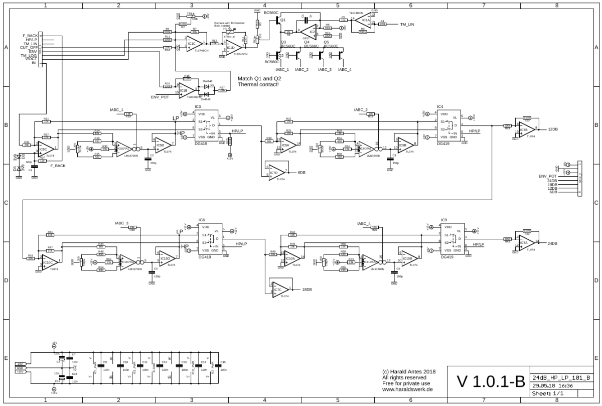
24dB VCF LP/HP schematic back PCB
Description:
Straight forward design. Four state variable filter cells are connected together in series, The output of each filter cell is brought out. There are a lot descriptions of those state variable filters out there. I feel no need to add another one. The resonance (Q) is voltage controlled with means of the OTA IC2OTA1 in the upper right corner (page 1). To compensate the volume loss when the resonance (Q) is turned up a second OTA (IC2OTA2) is used. This two OTA shares the same Iabc source. The amplification of this second OTA is increased when Q is going high and add volume to the output signal.
Calibration
DC offset OTA
- Refer to the procedure used for the 24dB VCF. Same procedure other with other part names.
-
Cut off frequency
- Apply a square signal of about 500Hz to the input. Set the filter to lowpass mode.
- Set potentiometer P7 (Cut off frequency) to max (15V). Set trimmer TR1 to ground.
- Listen to the output and/or use a oscilloscope at the 24dB output.
- Turn TR1 slowly to -15V. You will hear and see that the edges of the square signal starts rounding.
- Adjust TR1 so that there is no audible damping of the overtones. This adjustment is not critical. No need for excessive precision.
-
V/Octave
- Easiest way: Measure the voltage at the basis off transistor Q1. If you change the voltage at the V/Oct input 1V, the voltage at the basis of the transistor Q1 should change about 17mV. Adjust with TR2
- The other (precise) method needs an frequency generator and an oscilloscope. Not to mention some experienced knowledge. You need to measure the input and output signal amplitude. And do some math.
-
Feedback max
- Adjust TR1 to your liking
-
Gain loss compensation with high Q (Feedback)
- Adjust TR4 to your liking
Special parts
None
For best result match the OTA's for Gm
Known issues
None