Motivation
I was a bit hesitant doing this module because it uses the now obsolete LM1496 balanced modulator-demodulator. But you can still source them and I have some in my stock. So I decided to make a PCB and module for my Next Generation Formant project. I started with the original Elektor Formant schematic published in "Formant Erweiterungen" p35ff. I left out the microphone and envelope follower part because I already have such modules. I have added input buffers and raised the signal level to my 10Vpp used throughout my system. I was able to put two ringmodulator on a 50x100mm PCB.
Specs and features
- Dual ringmodulator
- 10Vpp input and output
- Runs on +/-15V and +/-12V
- Schematic ringmodulator
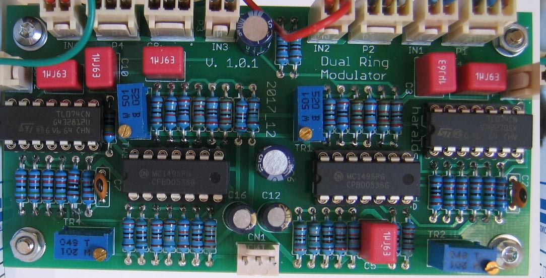
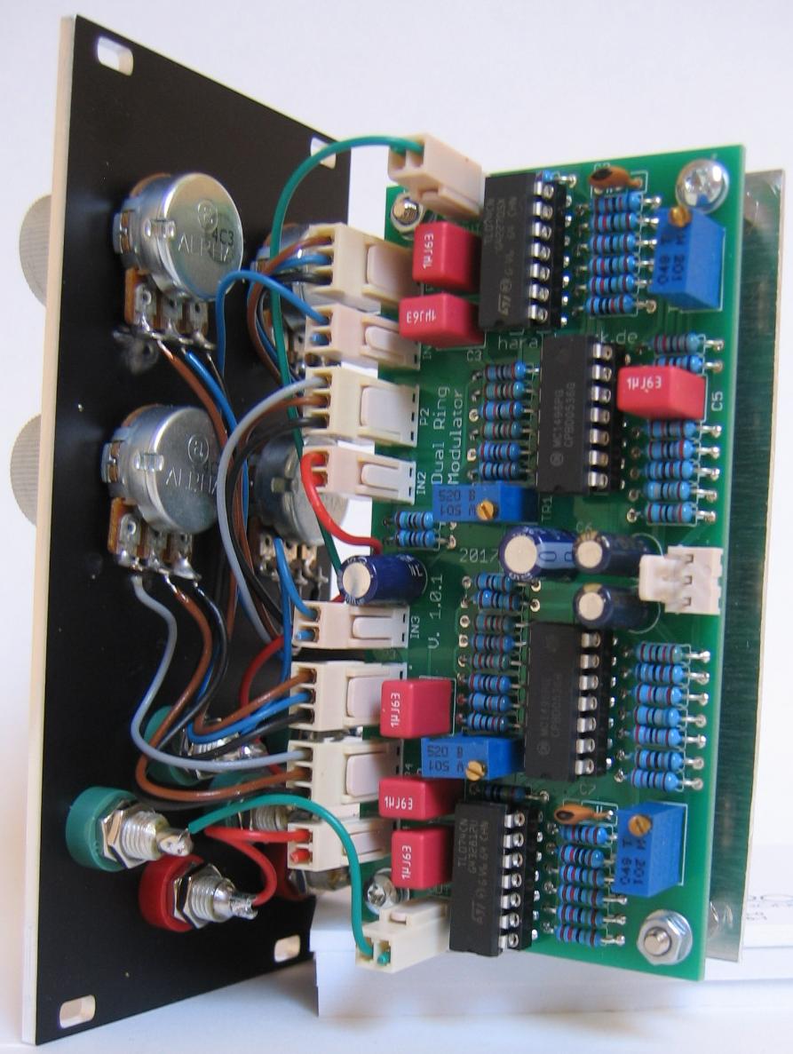
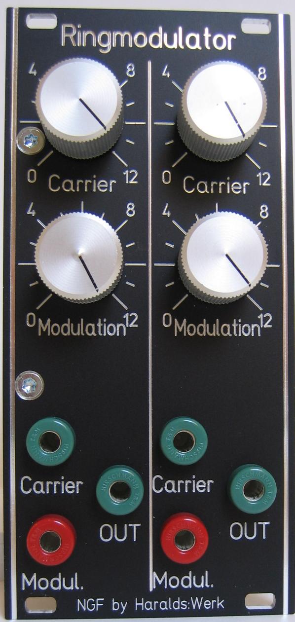
- Pictures
- Download docs
Implementation
Schematic
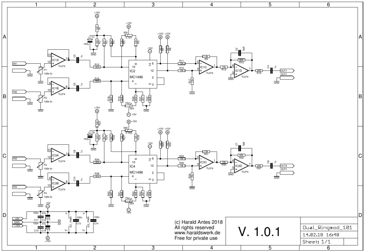
Dual Ringmodulator schematic
Description:
This implementation follows closely the original Elektor Formant implementation. Refer to the original documentation if needed. You can find it on the net. My changes are the input buffers and the adaption to my 10Vpp signal level.
Calibration
- You need to adjust the trimmers TR1..4. They are used for cancelling the input signal.
- Adjust a sine signal to about 1000Hz and 10Vpp signal level.
- Connect the signal to input IN1(IN2) ans adjust TR1(TR2) such that the input signal can no longer be heard or seen (if you use a oscilloscope) at the output.
- Do the same with the second Ringmodulator ( IN3, IN4, TR3, TR4, OUT2).
Special parts
- None. You can still source the LM1496.