Motivation

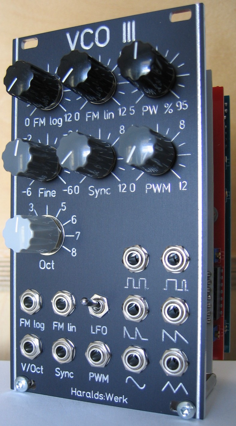
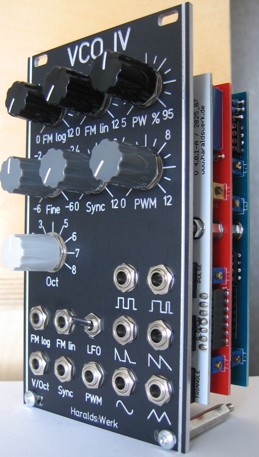
While looking at my rack I saw that I have all those advanced VCO like the Trapezoid Quadrature Through Zero, the Walsh 32 and the Harmonic Oscillator. So I was in need off a simpler and smaller VCO with just the basic wave forms. I have build two versions of this, VCO III and VCO IV. They share the control section and the waveshaper section. They differ in the core though. VCO III is build with the uA726, VCO IV with the 3046.
VCO IV is build with the 3046. The 3046 is again available as AS3046 so it should be easy to source.
Specs and features
- FM log input with attenuator
- FM lin input with attenuator
- PWM input with attenuator
- Sync input with attenuator
- Octave switch
- Fine frequency potentiometer
- LFO switch
- Square output
- Pulse output
- Spaced saw output
- Ramp down output
- Sine output
- Triangle output
- Runs on +/-15V and +/-12V
- Power consumption around 100mA each rail
Implementation
Schematic

VCO III / IV schematic: Control board

VCO III schematic: Main board

VCO IV schematic: Main board

VCO III / IV schematic: Waveshaper
Description:
Top
Calibration
- First make a gross test. You should have a signal at every output, pots and inputs reacting.
- 10V precision voltage source
- Measure the 10V at pin 6 at REF102 on PCB 4.0.1-A.
- Adjust TR1 for 10V.
- 3046 temperature adjust (VCO IV PCB 4.0.1-B only)
- For the temperature adjustment follow the procedure here: NGF VCO core two.
- If you want to measure the temperature directly you'll have to remove the control PCB and connect it with wires to the main PCB.
- Initial frequency
- Set octave switch to 1 (lowest).
- Set fine frequency to center.
- Adjust TR_2 (control PCB) to 27,5Hz (or what you prefer).
- Ramp adjust
- Connect an oscilloscope to the ramp output.
- Adjust TR2 for 10Vpp output
- Adjust TR3 for zero DC offset.
- Those adjustments are crucial for the following waveshaper.
- Triangle adjust
- Connect an oscilloscope to the triangle output.
- Adjust TR_1 for zero DC offset.
- This adjustments is crucial for the following sine waveshaper.
- Sine adjust
- Connect an oscilloscope to the sine output.
- Adjust TR_2 on the waveshaper PCB until the triangle rounds nicely to a sine. TR_3 adjusts the volume.
- Spaced saw adjust
- Connect an oscilloscope to the spaced saw output.
- Listen to the spaced saw output.
- Adjust TR_4 on the waveshaper PCB until you are satisfied with the sound.
- V/Oct adjust
- A procedure is found here:NGF: VCO Core two. You have to adapt the names for the trimmers.
- Finally readjust the initial frequency
- Set octave switch to 1 (lowest).
- Set fine frequency to center.
- Adjust TR_2 (control PCB) to 27,5Hz (or what you prefer).
Building hints
- Use long pin headers if you build the uA726 Version.
- I recommend using some kind of "windshield" for the uA726 and the 3046. For the uA726 I use a cut off syringe, for the 3064 a toy brick.
Special parts
- The transistor array CA3046 could be replaced with the available AS3046.
Download
VCO III / IV control board documentation downloadVCO III / IV control board Gerber files download
VCO III main board documentation download
VCO III main board 01 Gerber files download
VCO IV main board documentation download
VCO IV main board Gerber files download
VCO III / IV waveshaper documentation download
VCO III / IV waveshaper documentation download
VCO III front panel Gerber files download
VCO III front panel *.fpd files download
VCO IV front panel Gerber files download
VCO IV front panel *.fpd files download
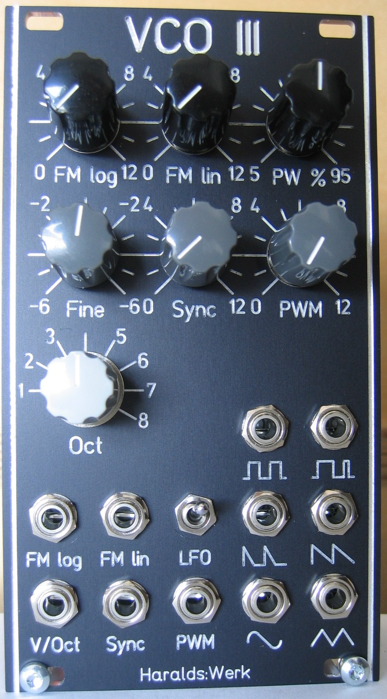
VCO III: Front view
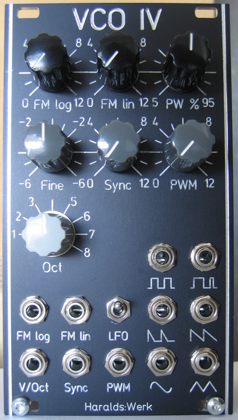
VCO IV: Front view
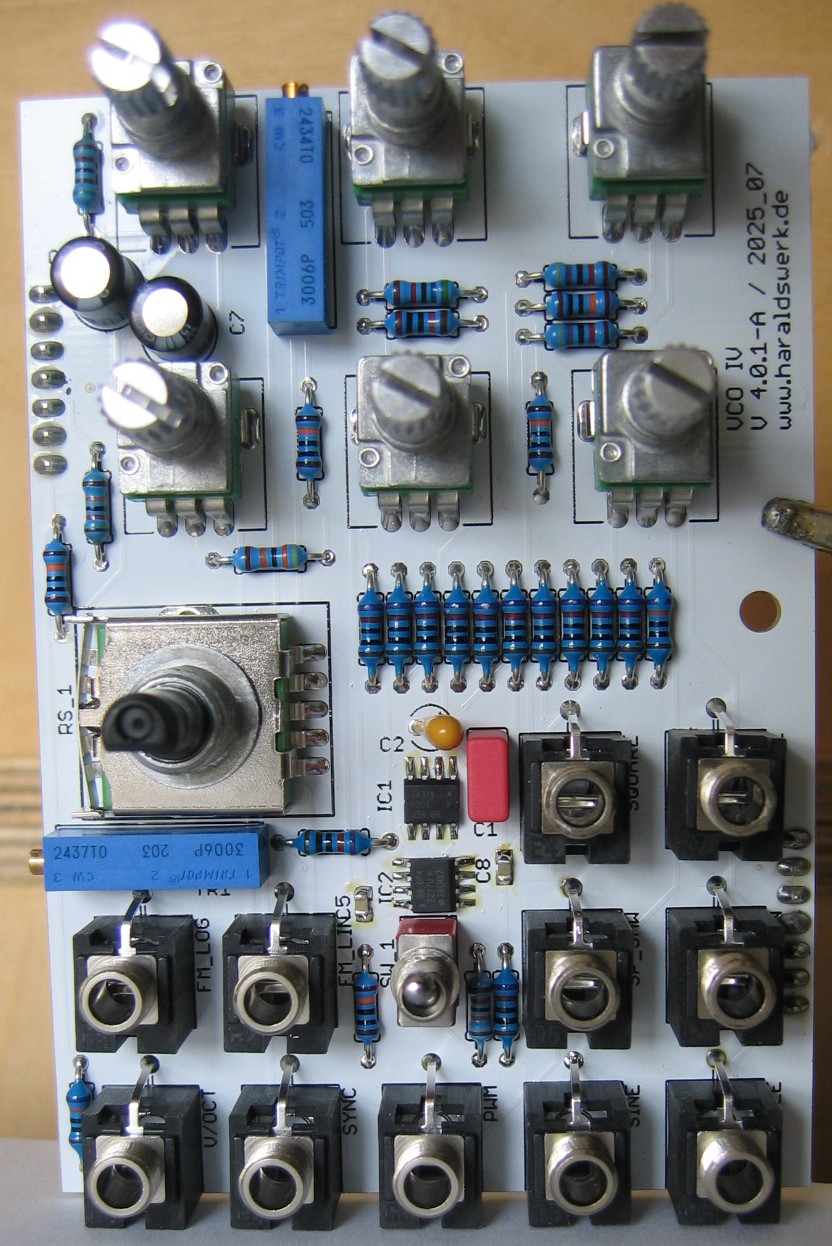
VCO III / IV: Populated control PCB
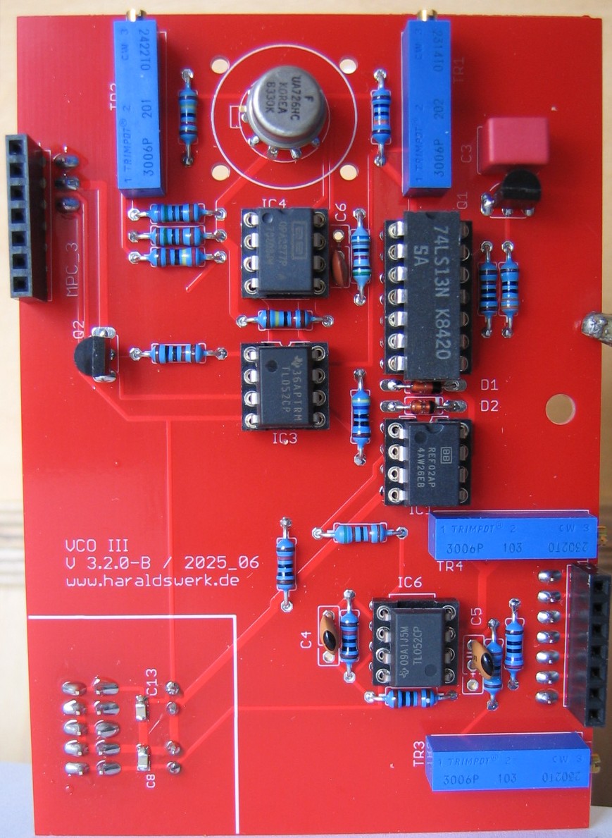
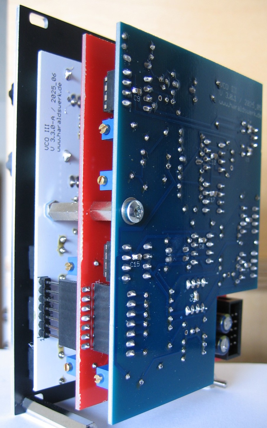
VCO III: Populated main PCB
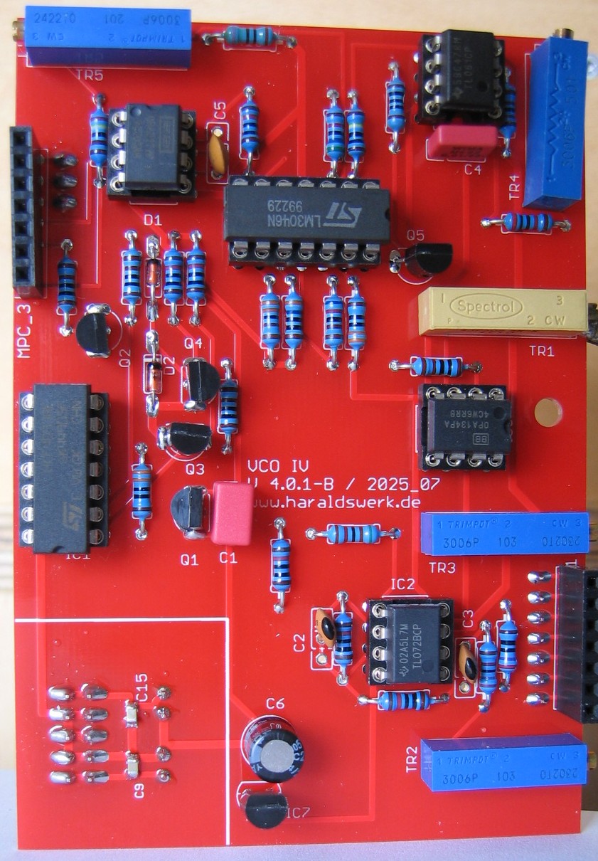
VCO IV: Populated main PCB
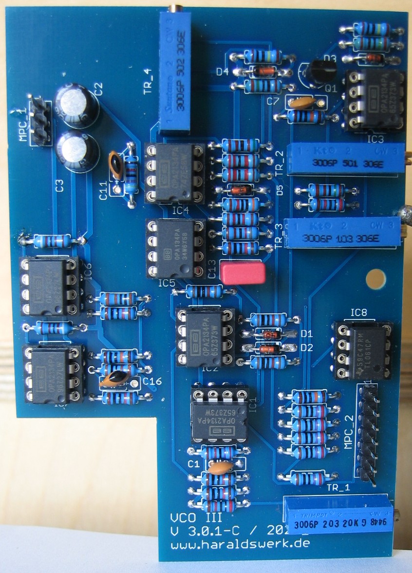
VCO III / IV: Populated waveshaper PCB
VCO III: Halve front view
VCO IV: Halve front view
VCO III: Halve back view
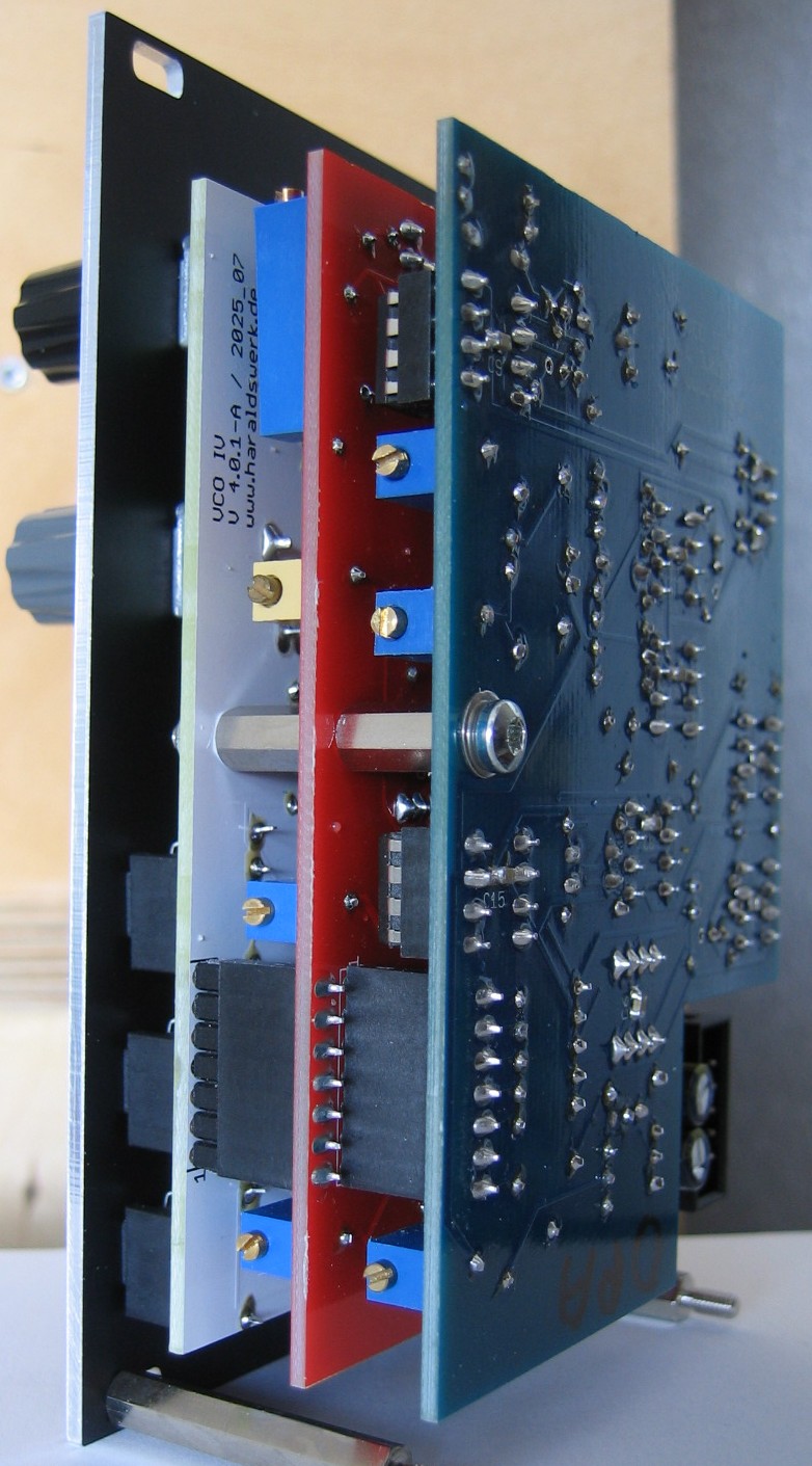
VCO IV: Halve back view
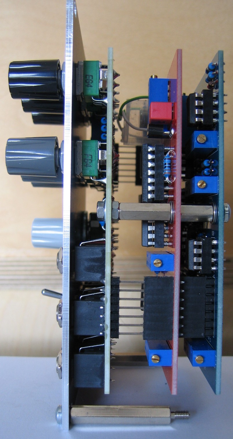
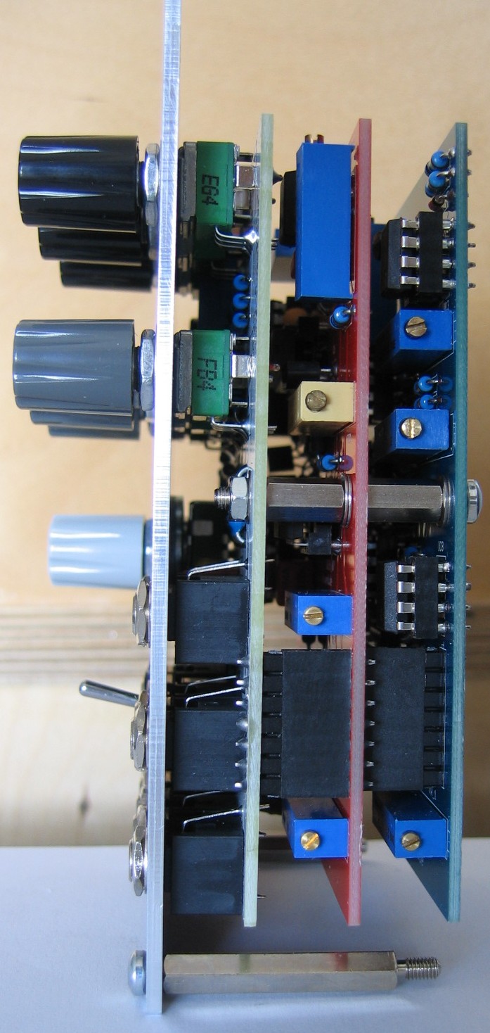
VCO III: Side view