Motivation

A well known way to reduce noise in VCA is using the VCA's in parallel. Here is my approach. A LM13700 used in parallel reduces the noise floor around 3dB.
Specs and features
- VCA with reduced noise floor
- Runs on +/-15V and +/-12V (with some resistors changed)
- Schematic VCA LN
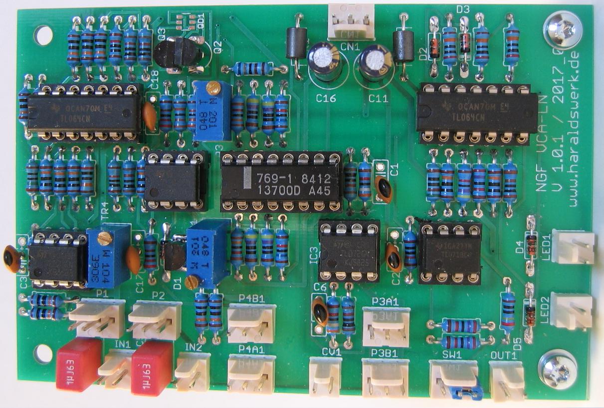
- Pictures
- Download docs
Implementation
Schematic
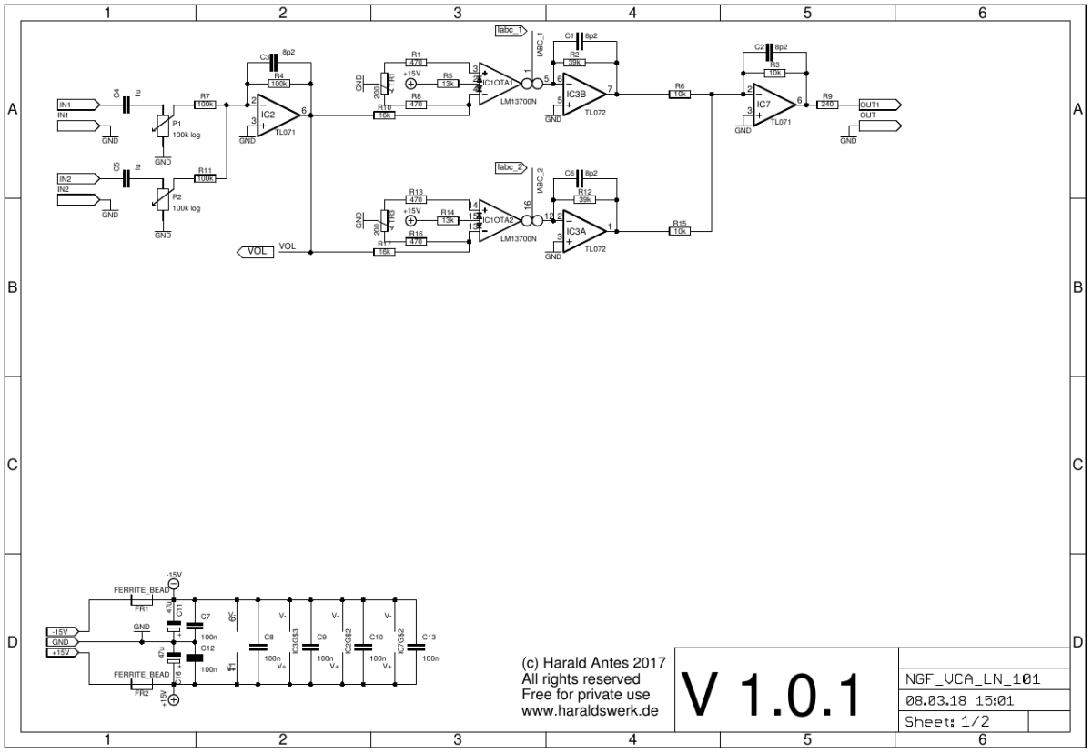
VCA LN schematic 01
Description:
Nothing special here. Just two plain forward designed VCA with LM13700. With the signals added together.
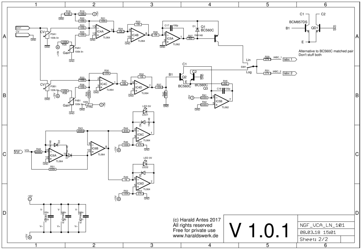
VCA LN schematic 02
Description:
Standard circuitry for Iabc and level control.
Calibration
- CV feedthrough: Remove IC3 and IC7. Set mode switch to lin, gain pot to max, input pot's to ground. Connect pin 7 from the socket of IC3 to ground. Measure the voltage at this point. Adjust TR1 for zero volts. Do the same with pin1 and TR3. Put the IC's back in.
- Log setpoint: Apply 5Vpp signal to the input. Set input pot to max. Set mode switch to log. Gain pot to ground. Adjust TR4 for zero signal output.
Special parts
- None.