Motivation
Not much to say. Just a unidirectional toggle switch. The input is switched between two outputs. Voltage controlled. Status signaled with LED.
Specs and features
- Buffered in and output
- Unidirectional
- Status signaled by LED
- Runs on +/-15V and +/-12V
- Power consumption below 15mA each rail
Implementation
Schematic

Voltage controlled toggle switch: Schematic control board
Description:
The interesting point here is the overvoltage protection for the control voltage input. This is done with the MCP6002 rail to rail operational amplifier. He is powered between GND and +5V. So, no negative or positve voltage above +5V will go through it. The diode in the input is not neede for voltage protection. The diode protects the voltage source when it supplies a negative voltage. Without the diode the negative signal is loaded by the input of the MCP600x. The 1M resistors are there to provide a defined potential.
Calibration
- None
Building hints
- None
Special parts
- You want to use the DG403 with the voltage range +/-15V. Check the datasheet. There are lower rated ones.
Download
VC Toggle Switch control board documentation downloadVC Toggle Switch control board Gerber files download
VC Toggle Switch *.fpd file
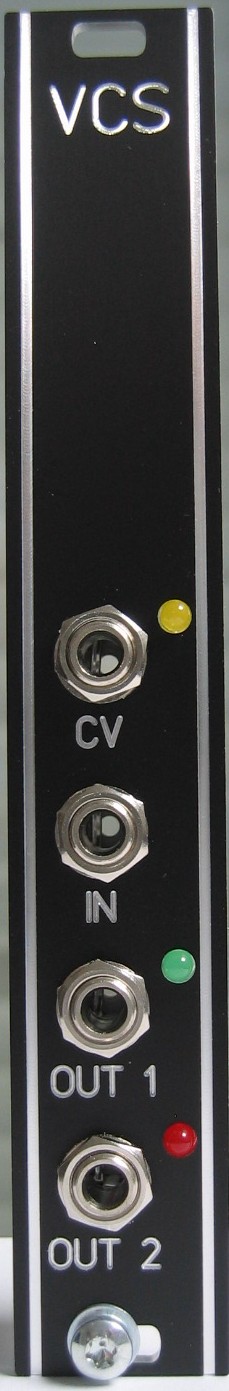
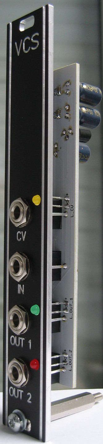
VC Toggle Switch: Front view
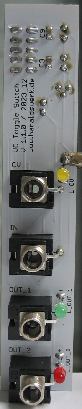
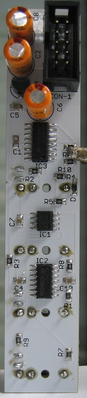
VC Toggle Switch: Populated control PCB front
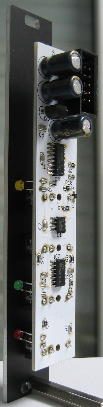
VC Toggle Switch: Populated control PCB back
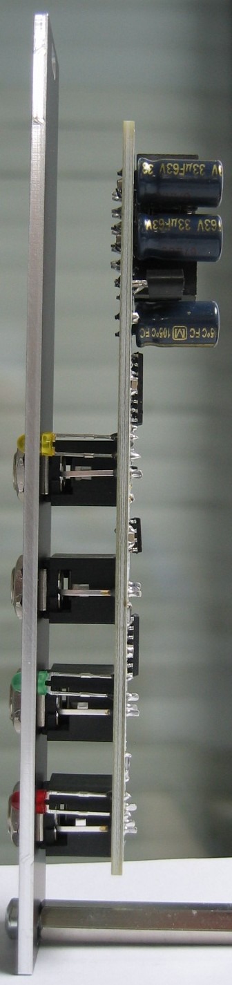
VC Toggle Switch: Halve side
VC Toggle Switch: Halve back