Motivation
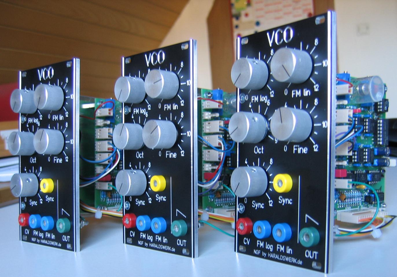
I have build my first original Elektor Formant VCO's in the 70's. They worked quite well and do so until today. Over the years i did implement some changes and extensions. Here i want to consolidate them in one PCB. I only implement the VCO core. The waveshapers will be part of another PCB. Anybody who wants to build this implemention should be aware that i use some obsolete parts here (uA726 and 74LS13). They are still accesible but it will take some research, afford and money to get hold of them. I removed the need for the +5V current supply, added an octave switch, FM lin, stabilized all internal control voltages, sync in and the improvements suggested in the second Format book.
In particular:
- Getting rid of the 5V current supply
- Stabilized control voltages
- Octave Switch
- FM lin
- Sync in
- 10Vpp output
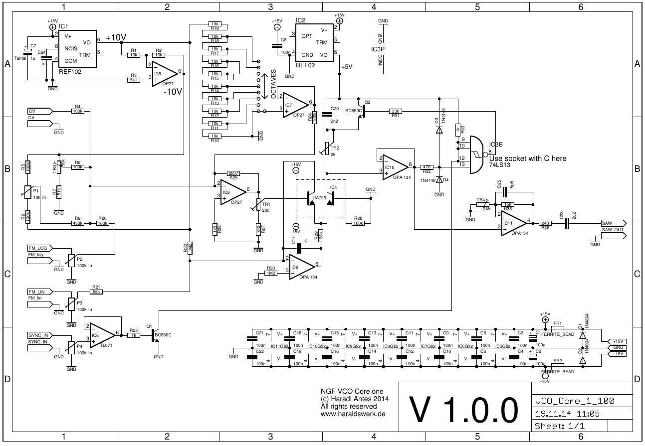
- Schematic
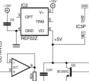
Getting rid of the 5V current supply
In the original VCO the pitch depends directly on the +5V current supply. If the voltage goes up the pitch goes down and vice versa. And the VCO's can possibly couple througt it. In a first step i replaced the direct connection with a + 5V voltage reference (REF02). But i still have to use the +5V rail for the 7413. When i switched to 74LS13 it was possible to use the REF02 for powering the 74LS13 as well. That done the +5V current supply was no longer needed.
Excerpt from the schematic:
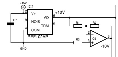
Stabilized control voltages
To avoid influence and coupling in the CV through the power rails all CV were stabiliced with REF102 to +10V. The -10V are generated with an OpAmp. The stabiliced voltages are used for the octave switch, the fine tuning pot, initial trimpot and stabilizing Iref for the uA726.
Excerpt from the schematic:
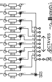
Octave Switch
I found it usefull to have an octave switch. This is accomplished with an rotary switch, some resistors and a buffer. The resistors should be matched. I did hand match them to 0,1%.
Excerpt from the schematic:
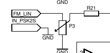
FM lin
FM lin is easily added with one pot and one resistor. The ressitor is direct connected to the negativ input of IC9
Excerpt from the schematic:
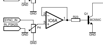
Sync in
Sync in is added with means of an OpAmp a resistor and a transistor.
Excerpt from the schematic:
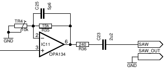
10Vpp output
For better signal to noise ratio throughout the system i enhanced the signal level to 10Vpp
Excerpt from the schematic:
Calibration
- t.b.d
Special parts
As mentioned earlier there the obsolet parts uA726 and 74LS13. And the resistors for the octave swithc should be selected to 0,1%.