Motivation
This is basically a combination of 6 VCA configured as a mixer. The five inputs can be used as individual linear VCA or as input channels to the mixer output. All five input channels and the mixer output are voltage controlled. The control voltage inputs for the input channels are normalized so you can modulate all five channels with the same control voltage or group them to your needs. The sliders controls the amount of the modulation per channel. The inputs are normalized as well. This makes for a nice voltage controlled overdrive when used. A level indicator shows the output signal at the summed output. The summed output is voltage controlled as well. Instead of the here used CA3280 (I am using up some NOS) you can use the new available AS3280.
Specs and features
- Five voltage controlled inputs
- Five independent VCA
- Voltage controlled output
- Level indicator
- Power consumption around 75mA each rail
Implementation
Schematic

Voltage controlled mixer-VCA schematic: Control board

Voltage controlled mixer-VCA schematic: Main board
Description:
On the schematics you can see 6 VCA with linear control current sources. Just as it is done over and over again. Plenty explanations on the web.
Calibration
- Set all Bias potentiometers to zero
- Attach a voltmeter or oscilloscope to the summed output
- Set output Bias potentiometer to max
- Adjust TR2 for zero Volt at the output
- Let the output Bias potentiometer stay at max
- Set the Bias potentiometer of channel one(2, 3, 4, 5) to max
- Adjust TR1 (TR3, TR4, TR5, TR6) for zero Volt at the output
- Set the Bias potentiometer of channel one(2, 3, 4, 5) to back to zero
Building hints
- It is mechanical a bit tricky. Before mounting the sliders make a check of the functionality because you'll have a hard time replacing parts on the backside of the front PCB with solder joints under the sliders.
- Now mount the sliders. Do not solder them yet!!. Put the front panel on and tighten the screws.
- Put a (scrap) piece of PCB material or something else with 1.6mm thickness between sliders and front panel
- Turn the module upside down and push the sliders against the scrap material and the front panel.
- Make sure that they are parallel to the front
- The solder legs are now nearly flush with the back side of the PCB
- Check again that the sliders don't touch any solders joints beneath them.
- Solder the sliders
Special parts
- Instead of the here used CA3280 (I am using up some NOS) you can use the new available AS3280.
- The sliders are from Befaco (Thonk)
- The connectors are Thonkicons (Thonk)
Download
Voltage controlled mixer-VCA control board documentation downloadVoltage controlled mixer-VCA control board Gerber files download
Voltage controlled mixer-VCA main board documentation download
Voltage controlled mixer-VCA main board Gerber files download
Voltage controlled mixer-VCA *.fpd file
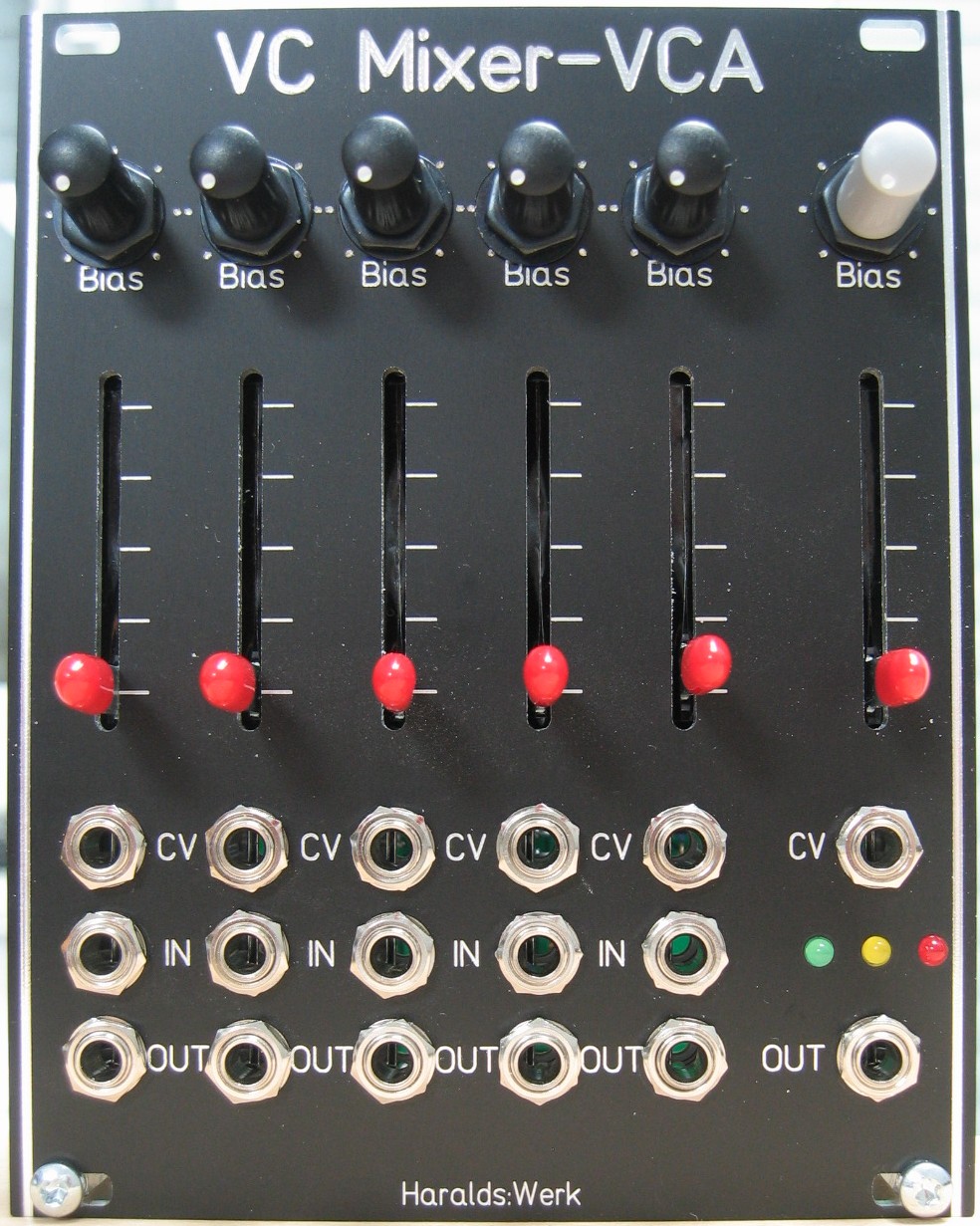
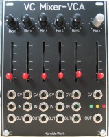
Voltage controlled mixer-VCA: Front view
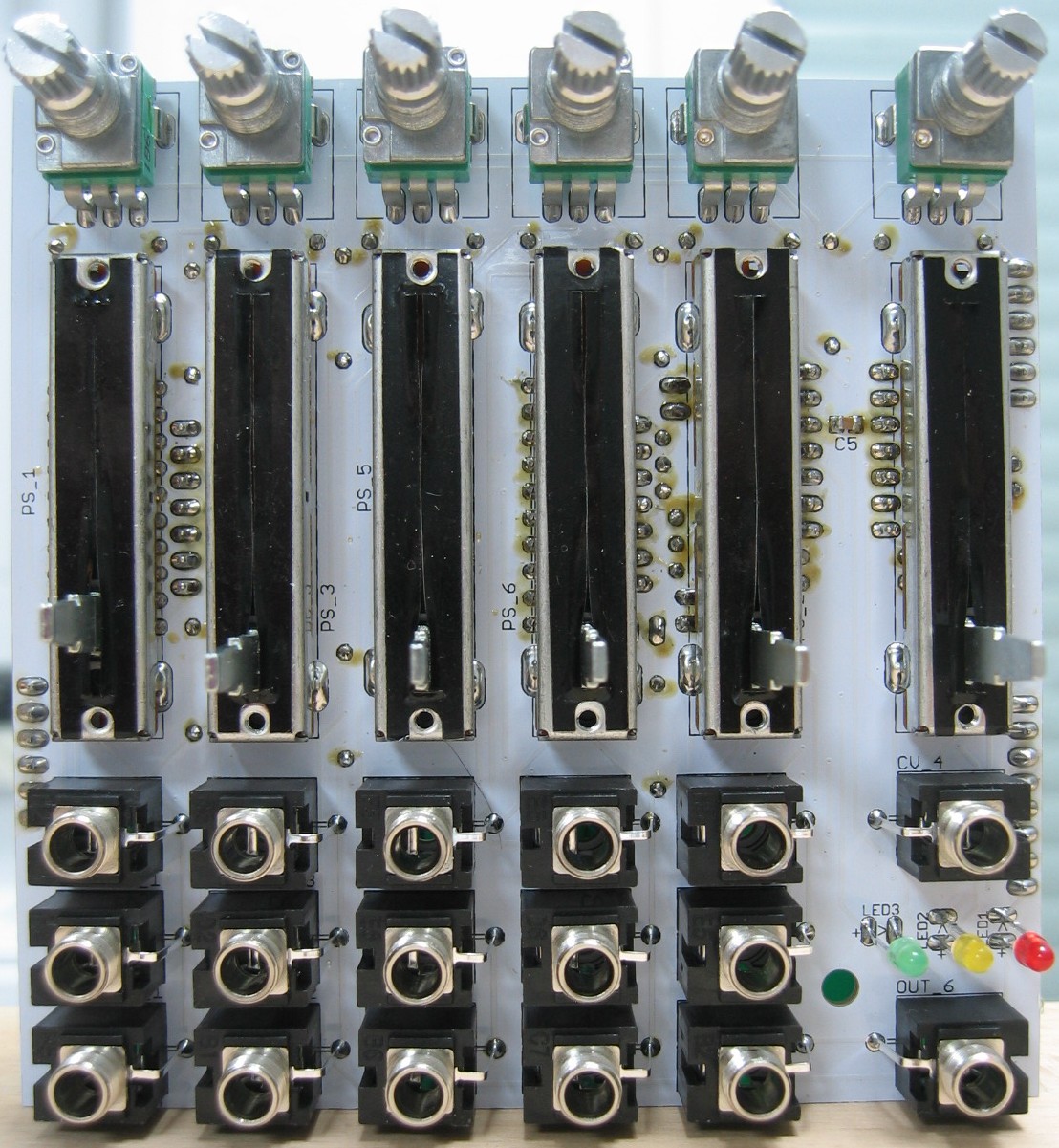
Voltage controlled mixer-VCA: Populated control PCB front
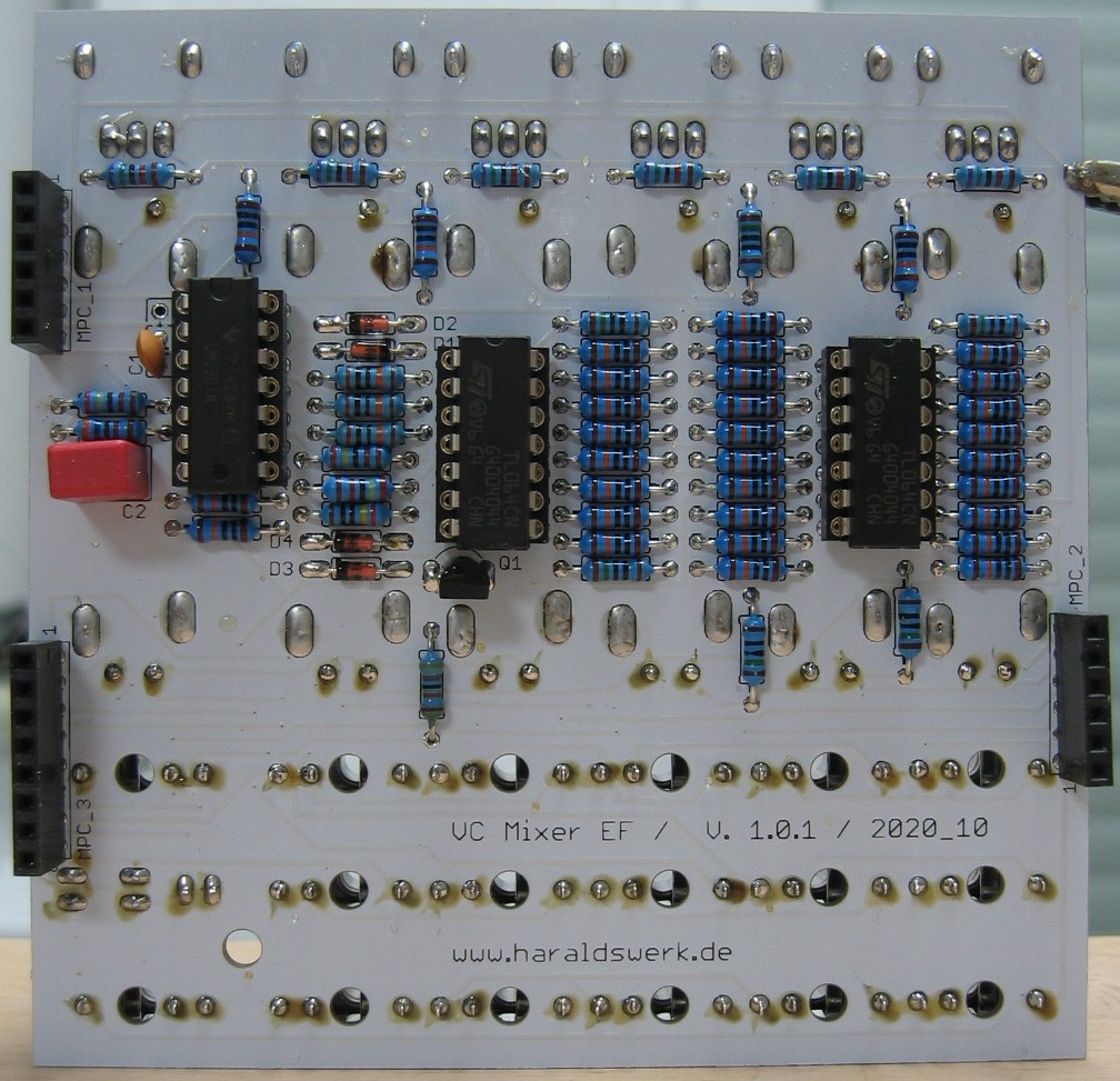
Voltage controlled mixer-VCA: Populated control PCB back
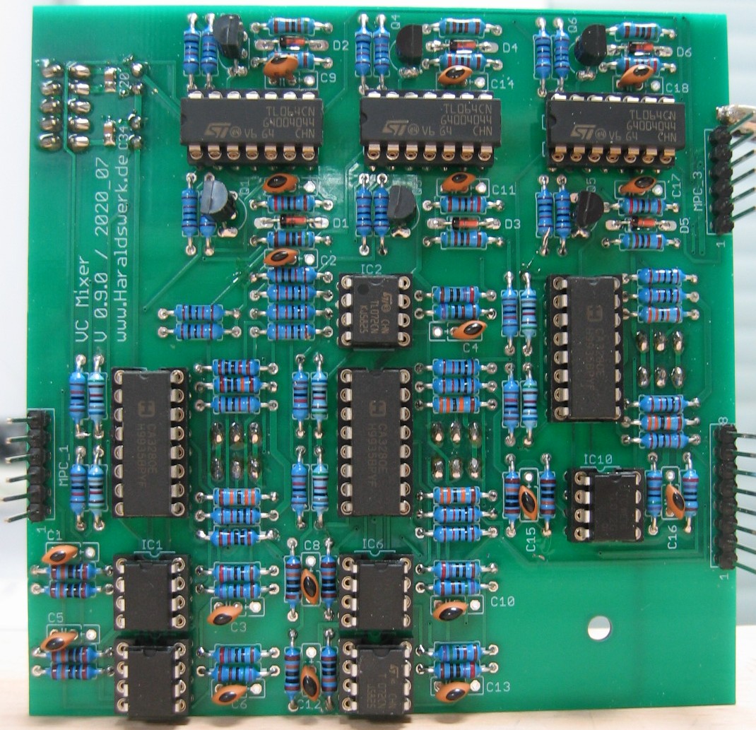
Voltage controlled mixer-VCA: Populated main PCB
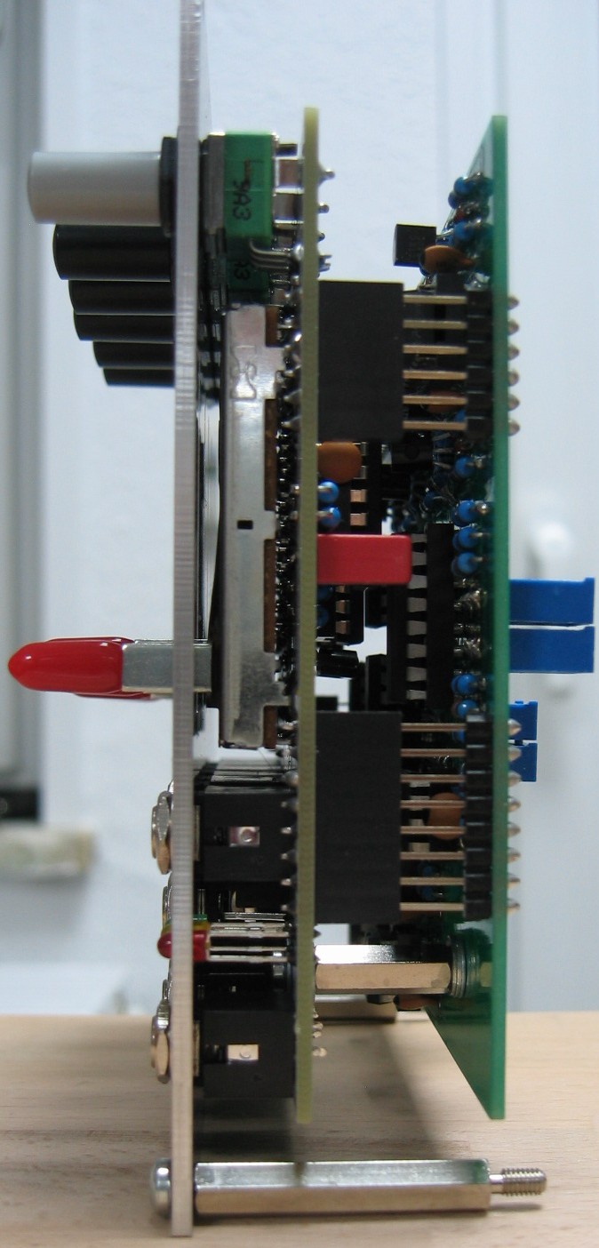
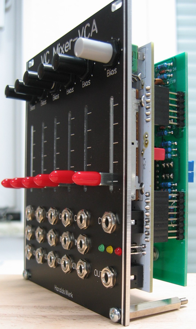
Voltage controlled mixer-VCA: Side view