Motivation
This scanning mixer is derived from the work of Jürgen Haible and Don Tillman with a lot off additions, changes and expansions.. The mixer is able to scan through four inputs with variable depth ans position. Manually and CV controlled. You can overdrive the individual channel nicely to add some overtones per channel. Rate, depth and scan amount are voltage controllable. The mixing level is controlled with sliders and voltage controllable as well. The four channels are summed into an output channel with similar controls.
The scanning mixer comes in two flavours linear and logarithmic. The linear scan gives a more smooth transition between the channels. The logarithmic scan gives a steeper separation between channels. All channels are DC coupled. So you can get interesting slowly moving CV textures when slowly scanning through different LFO outputs. When the depth potentiometer is set to zero you can use this module as simple voltage controlled mixer
Specs and features
- Four input channels
- DC coupled
- Overdrive per channel
- Variable scan depth and position
- Voltage controlled rate, depth and scan amount
- Mixing level voltage controllable
- Power consumption below 80mA each rail
Implementation
Schematic

Scanning Mixer schematic: Control board

Scanning Mixer schematic: Main board for linear scanning 01

Scanning Mixer schematic: Main board for linear scanning 02

Scanning Mixer schematic: Main board for linear scanning 03

Scanning Mixer schematic: Main board for logarithmic scanning 01

Scanning Mixer schematic: Main board for logarithmic scanning 02

Scanning Mixer schematic: Main board for logarithmic scanning 03

Scanning Mixer schematic: Main board two
Description:
Tbd.
Calibration
- Set manual potentiometer to max left (zero)
- Set depth potentiometer to zero
- Attach a voltmeter or oscilloscope to the summed output
- Set the four channel sliders to zero
- Set the output channel slider to max
- Adjust TR_1 on main PCB 01 for zero Volt at the output
- Let the output channel slider stay at max
- Set the channel slider of channel one (2, 3, 4) to max
- Adjust TR_1 (TR_2, TR_3, TR_4) on main PCB 02 for zero Volt at the output
- Set the channel slider of channel one (2, 3, 4) to back to zero
- Move to next channel
Building hints
- It is mechanical a bit tricky. Before mounting the sliders make a gross check of the functionality because you'll have a hard time replacing parts on the backside of the front PCB with solder joints under the sliders.
- Now mount the sliders. Do not solder them yet!!. Put the front panel on and tighten the screws.
- Put a (scrap) piece of PCB material or something else with 1.6mm thickness between sliders and front panel
- Turn the module upside down and push the sliders against the scrap material and the front panel.
- Make sure that they are parallel to the front
- The solder legs are now nearly flush with the back side of the PCB
- Check again that the sliders don't touch any solders joints beneath them.
- Solder the sliders
- Use long standoffs to connect the front PCB with the main PCB
Special parts
- Instead of the here used CA3280 (I am using up some NOS) you can use the new available AS3280.
- The sliders are from Befaco (Thonk or Befaco)
- The connectors are Thonkicons (Thonk)
Download
Scanning Mixer control board documentation downloadScanning Mixer control board Gerber files download
Scanning Mixer main board 01 linear documentation download
Scanning Mixer main board 01 linear Gerber files download
Scanning Mixer main board 01 logarithmic documentation download
Scanning Mixer main board 01 logarithmic Gerber files download
Scanning Mixer main board 02 documentation download
Scanning Mixer main board 02 Gerber files download
Scanning Mixer *.fpd file
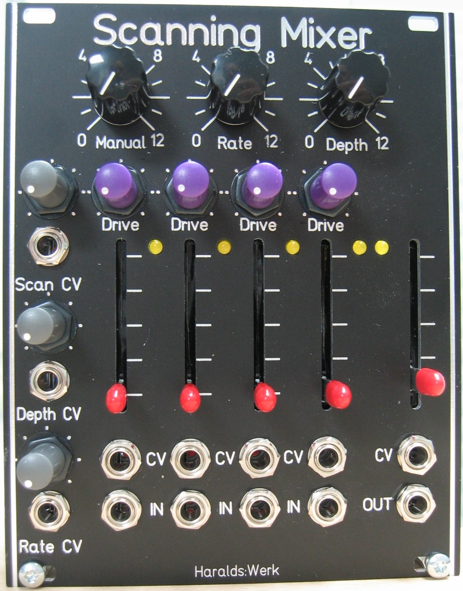
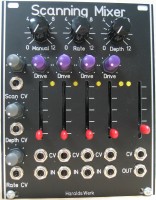
Scanning Mixer: Front view
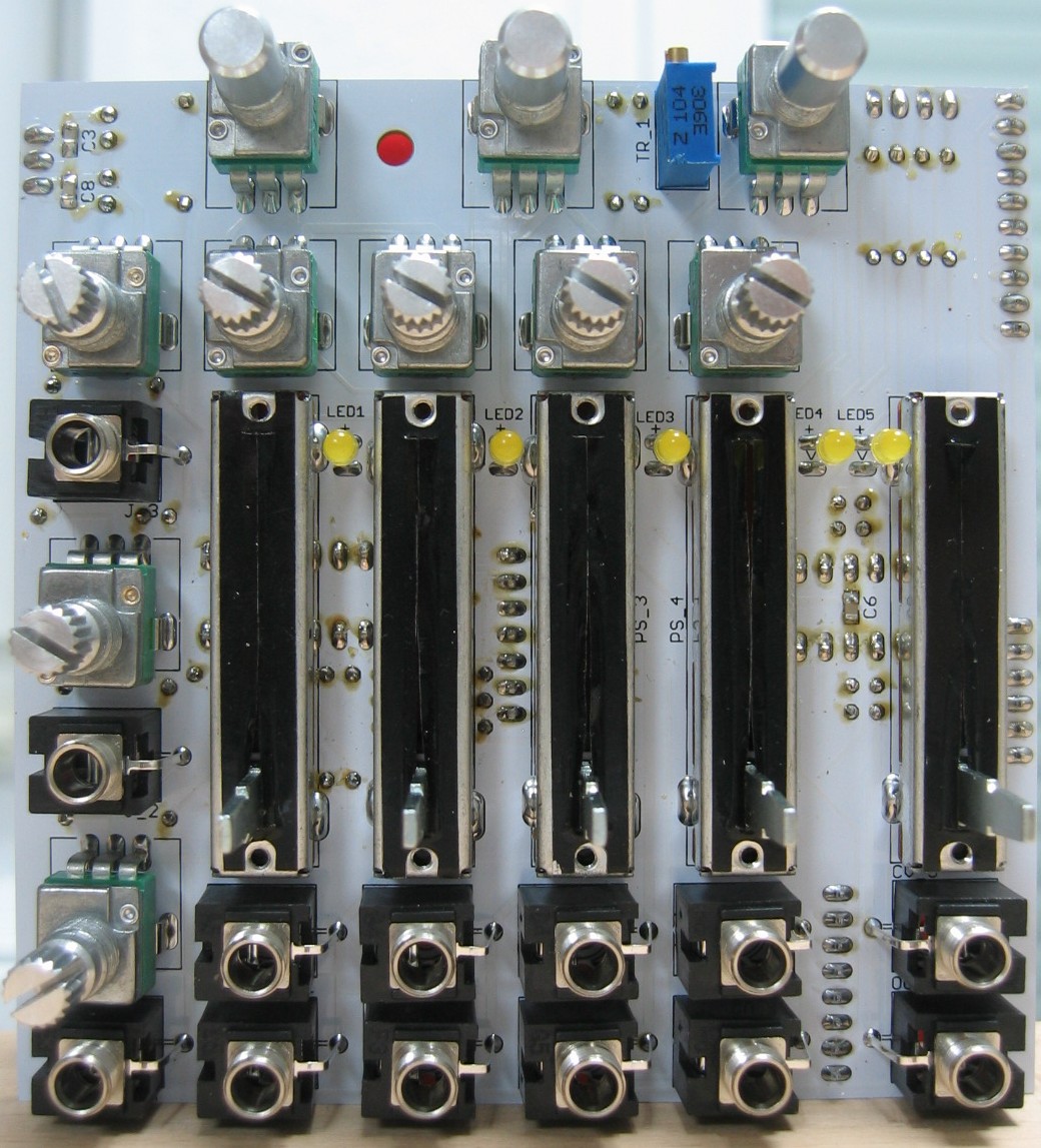
Scanning Mixer: Populated control PCB top
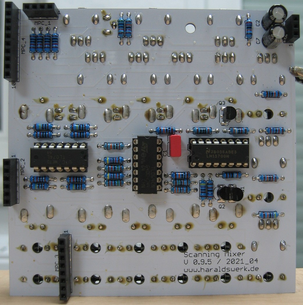
Scanning Mixer: Populated control PCB back
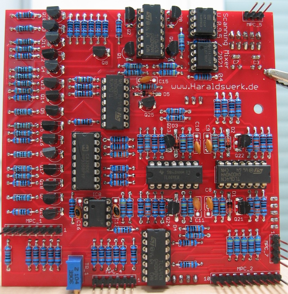
Scanning Mixer: Populated main PCB 01 linear
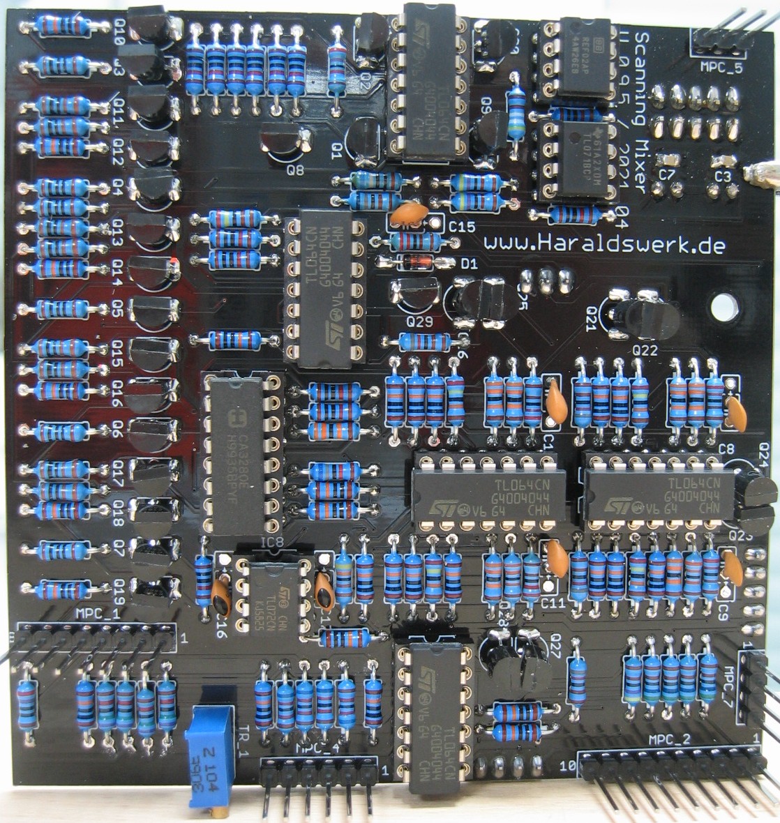
Scanning Mixer: Populated main PCB 01 log
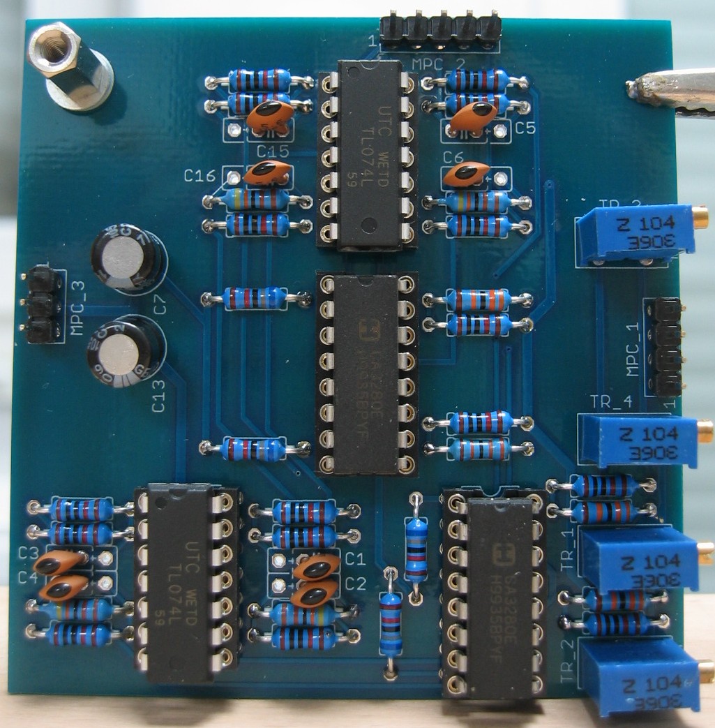
Scanning Mixer: Populated main PCB 02
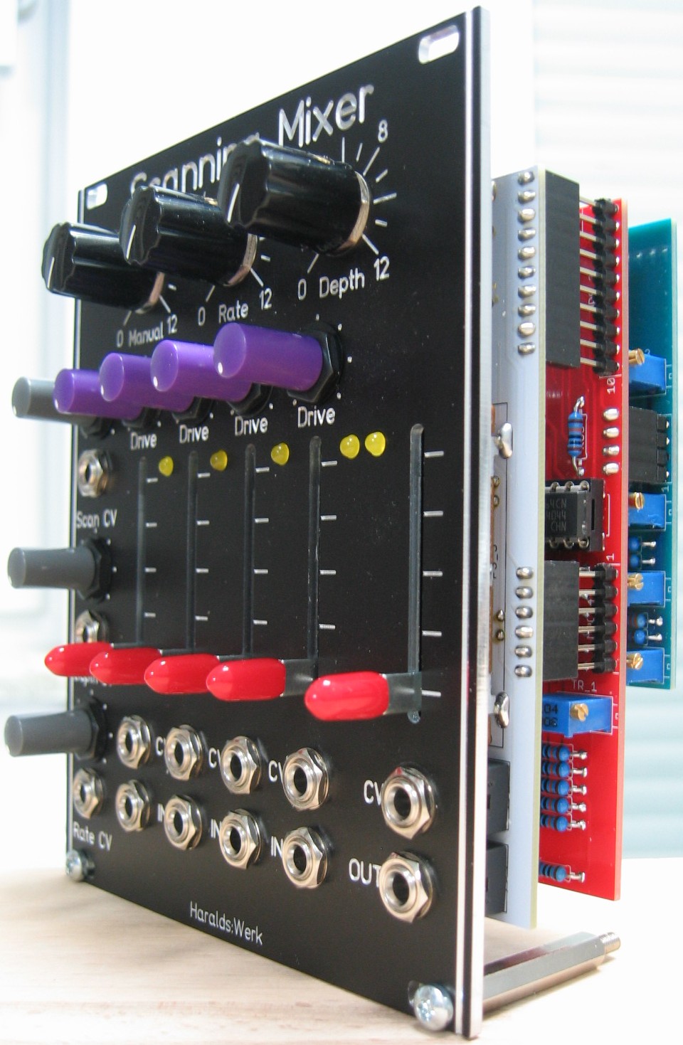
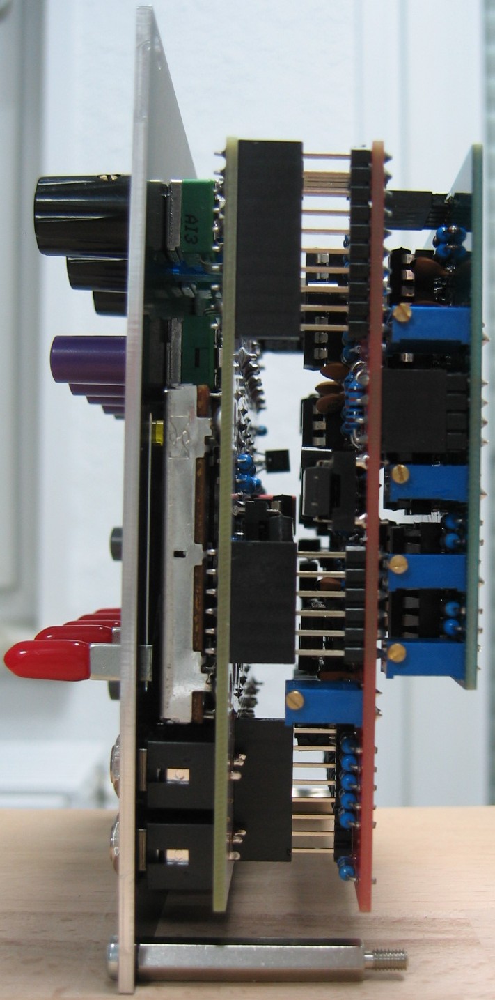
Scanning Mixer: Half front view
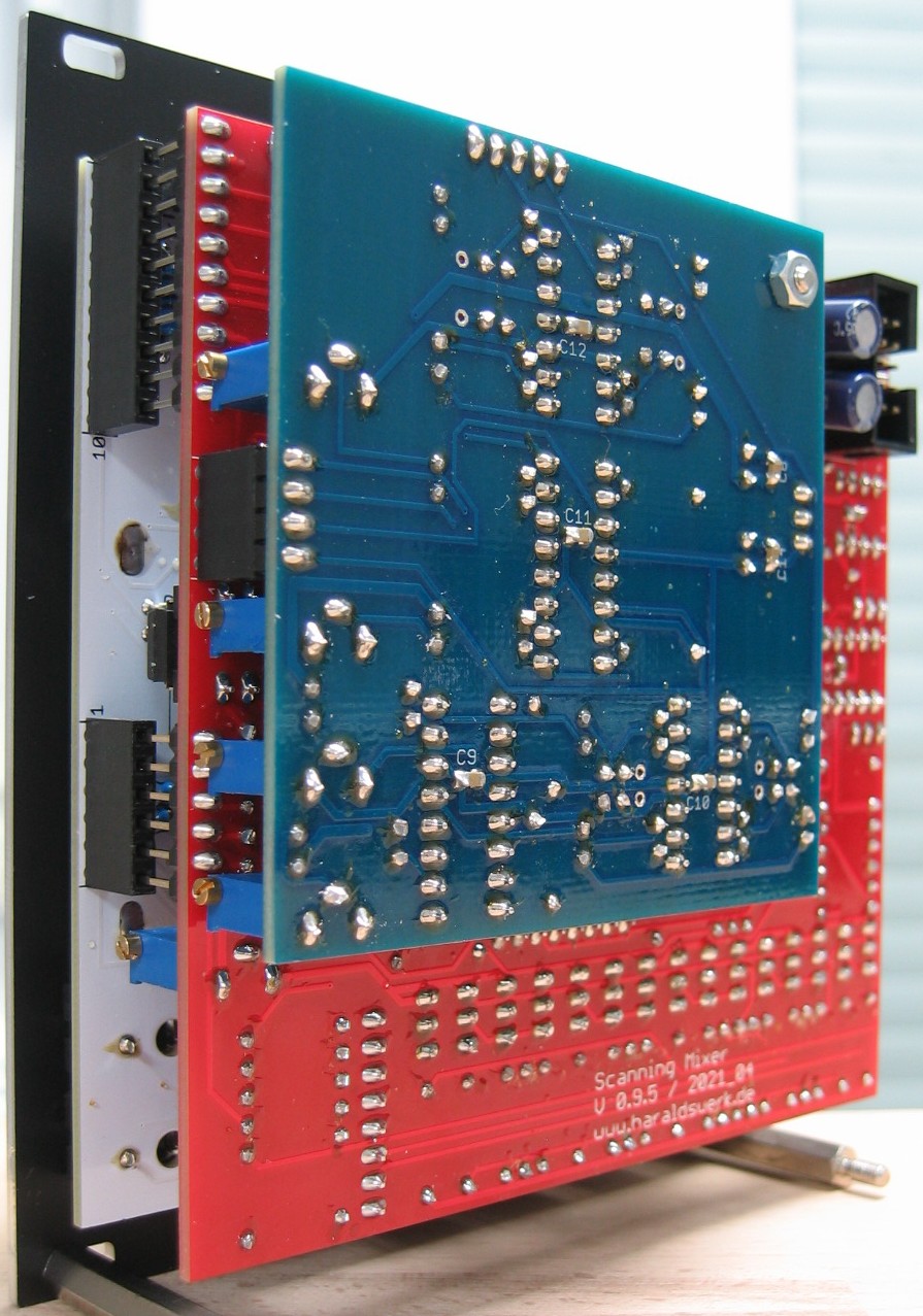
Scanning Mixer: Back view