Motivation
This logic module takes up to four input signals and outputs the logic function AND, OR, XOR dependent on the input signals. The inputs are normalized so you can use less then the four inputs. It has three NOT functions as well.
Every input signal above +2.5V is logic high, below +2.5V logic low. The output is 5V logic high, 0V logic low. This module is mainly thought for processing gate and trigger signals but can be used with audio signals as well. If used in the audio range the output is a pulse train between 0V and 5V with variable duty cycle dependent on the input signals and the output used.
Specs and features
- Up to four input signals
- Logic input level above +2.5V is high, below is logic low
- AND, OR, XOR parallel out
- Three NOT functions
- Logic output level +5V high, 0V logic low
- Runs on +/-12V and +/-15V
- Power consumption below 30mA positive rail. 5mA negative rail.
Implementation
Schematic

Logic II: Schematic control board

Logic II: Schematic main board
Description:
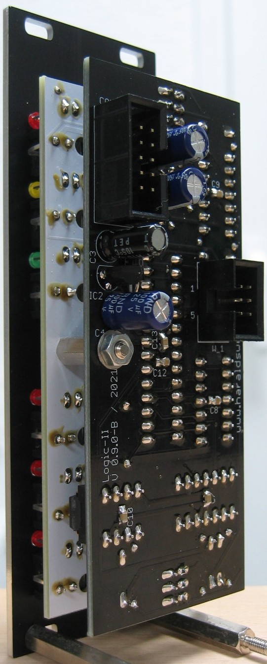
Nothing special to mention. On page one you see the input and outputs. On page two are the input protection circuitry, the microprocessor and the output buffers. The logic is done in software.
Calibration
- None
Building hints
- None
Special parts
- None
Download
Not available
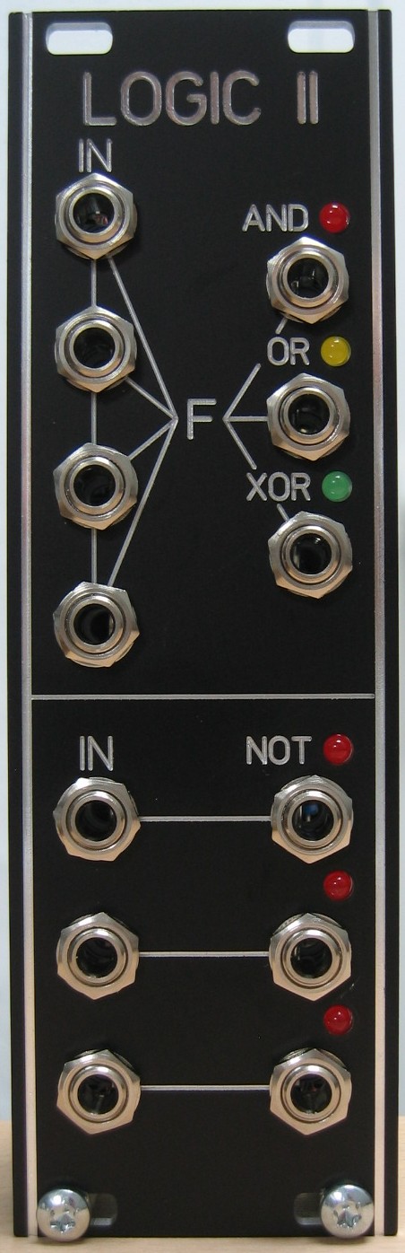
Logic II: Front view
Logic II: Populated control PCB
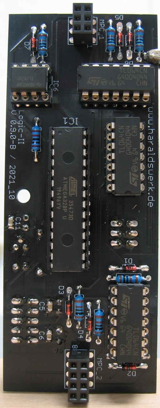
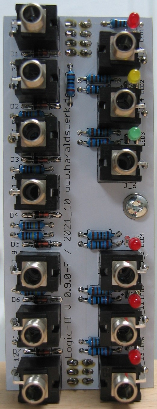
Logic II: Populated main PCB
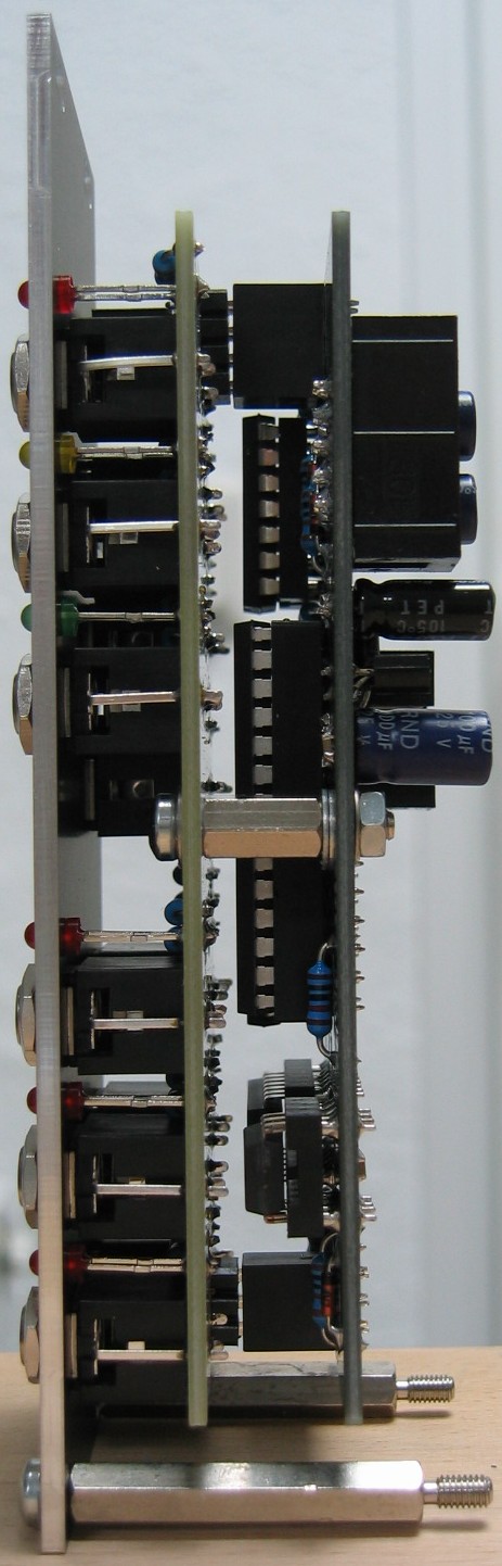
Logic II: Back view
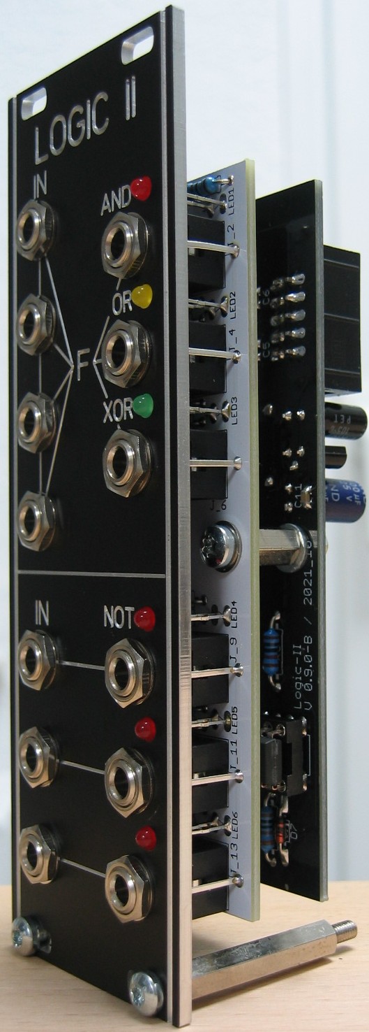
Logic II: Half front view