Motivation
A gate to trigger converter can be used in multiple ways. This device can not only convert gate to trigger signals. It converts any fast enough rising positive edge from a signal in a trigger pulse. The trigger pulse length is independent from the input signal. The trigger length is determined by one capacitor and is easily adjusted to your needs.
Specs and features
- Input: positive Gate or any fast changing voltage.
- Output: short 5V pulse. Length and voltage adaptable
- PSU +15V/-15V or +12V/-12V
- Schematic
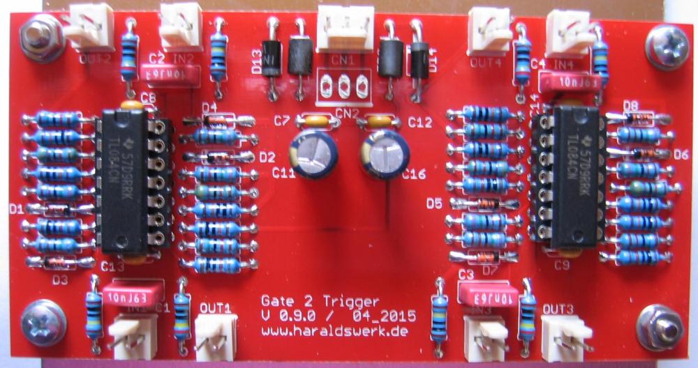
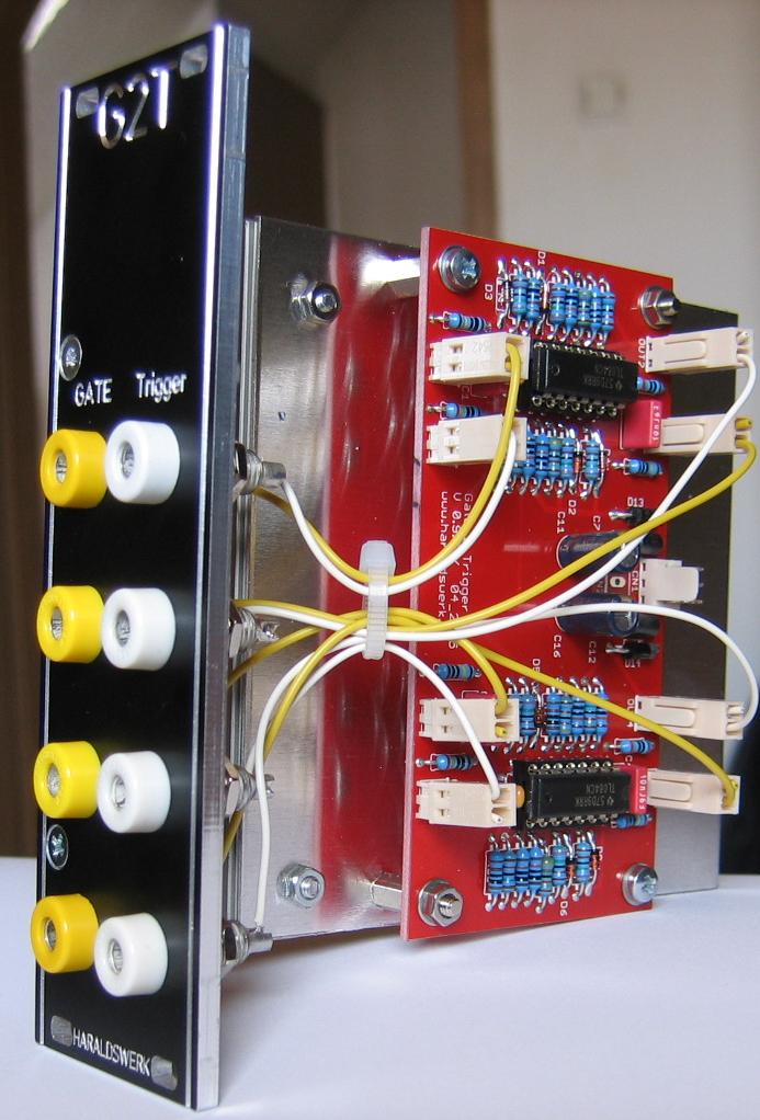
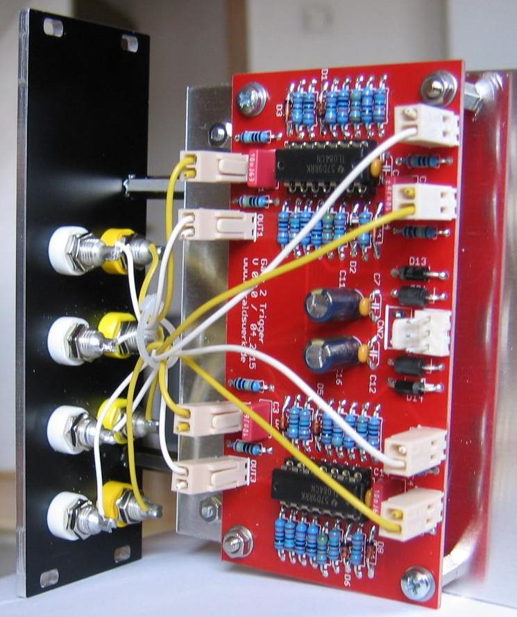
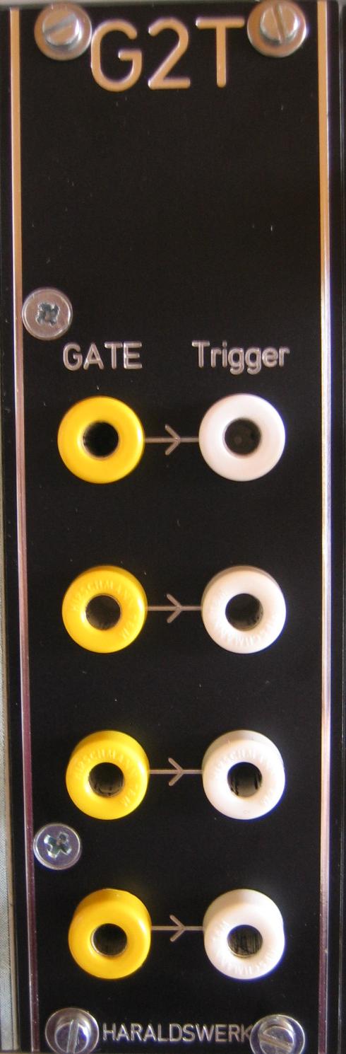
- Pictures
- Gate to Trigger Documentation download
Implementation
Schematic
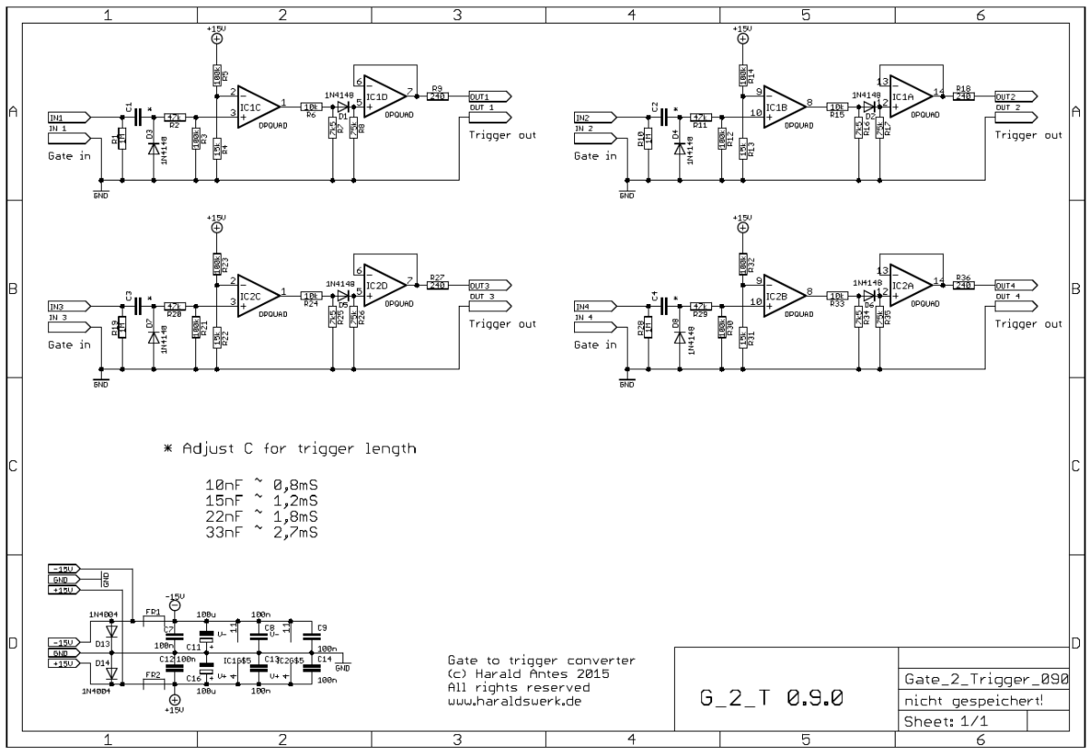
Gate to Trigger converter schematic
Description:
Those four gate to trigger converter are functionally identical. The input network converts a fast enough rising edge of a positive going signal into a brief positive going pulse. The following op-amp wired as comparator cleans the resultant pulse and forms a square pulse. The second stage cuts of the negative part, shift the output level down to 5V and buffers the output. The trigger pulse lengths is adjusted be changing the value of the input capacitor. The output level can be adjusted with the voltage divider at the output of the first op-amp
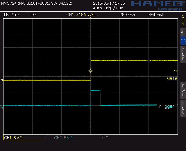
Screenshot - Gate: yellow, Trigger: blue
Calibration
- None
- Use appropriate C values for the trigger length you want
Special parts
None
Download
Gate to Trigger Documentation