Motivation
This is the Eurorack version of my NGF 36dB VCF. I have brought out the 6dB, 12dB, 18dB, 24dB, 30dB and 36dB poles. You have two audio inputs for easy mixing sound sources. And CV inputs for linear TM, log TM, envelope, V/Oct tracking and emphasis. The exponential circuit is temperature compensated with KTY81-110. If the 12dB output is patched back to input 2 the filter can serve as a sine oscillator.
Specs and features
- 36dB voltage controlled low pass and high pass filter
- Two inputs for easy mixing
- 6dB, 12dB, 18dB, 24dB 30dB, 36dB output
- HP/LP switch
- Positive and negative ENV control with sign changer
- Temperature compensation with KTY81-110
- CV inputs for linear TM, log TM, envelope, V/Oct tracking and emphasis
- Usable as sine oscillator
- Runs on +/-12V and +/-15V (with minor resistor value changes for best performance)
- Power consumption around 60mA negative rail, 65mA positive rail
Implementation
Schematic

6..36dB VCF schematic: Main board

6..36dB VCF schematic: Control board
Description:
Straight forward design. Six state variable filter cells are connected together in series, The output of each filter cell is brought out. There are a lot descriptions of those state variable filters out there. I feel no need to add another one.
Calibration
- OTA DC offset
- Set all potentiometers to zero.
- The order is crucial. Always start with MP_1/TR_1 (Note MP_1 and MP-1 are not the same).
- Measure the output voltage at MP_1 (MP_2, MP_3, MP_4, MP_5, MP_6)
- Adjust trimmer TR_1 (TR_2, TR_3, TR_4, TR_5, TR_6) to zero Volt (on backside main PCB).
- Don't forget the the feedback OTA. Measure at MP-1 and adjust TR8 (Note MP_1 and MP-1 are not the same).
- Initial frequency
- Apply a sine with 10Vpp and the lowest frequency you want to filter to the input (Most common 20..40Hz).
- Close the Cut off pot completely. No feedback.
- Adjust Trimmer TR_1 (control PCB) for zero output with a scope.
- I use the 12dB output here. Which means you'll still have some signal bleed through at the 6dB output. If you don't like this use the 6dB output here.
- Feedback strength
- Apply a signal to the input. 100Hz square is a good start.
- Turn the feedback potentiometer to maximum.
- Adjust TR7 (on backside main PCB) to the max amount of feedback you like. Try different signals.
- V/Octave
- Connect the 12dB output to input 2. No external signal in input 1.
- Turn input2-, cut-off- and feedback potentiometer to 3/4.
- You should see a sine at the 36dB output (and others). If not increase the pot-settings.
- Adjust output volume with input2 pot to 10Vpp
- Turn the frequency down to around 100Hz with cut-off potentiometer
- Apply the control voltage to the V/Oct input (Keyboard, precision voltage source).
- Doubling the voltage should double the frequency. Adjust TR_2 (control PCB) until it works.
Building hints
- The LM13700 differ in quality from part to part. You might want to select the IC for lowest DC output swing.
- Match transistor Q1 with Q2
Special parts
- None
Download
6..36dB VCF main board documentation download6..36dB VCF main board Gerber files download
6..36dB VCF control board documentation download
6..36dB VCF control board Gerber files download
6..36dB VCF *.fpd file download

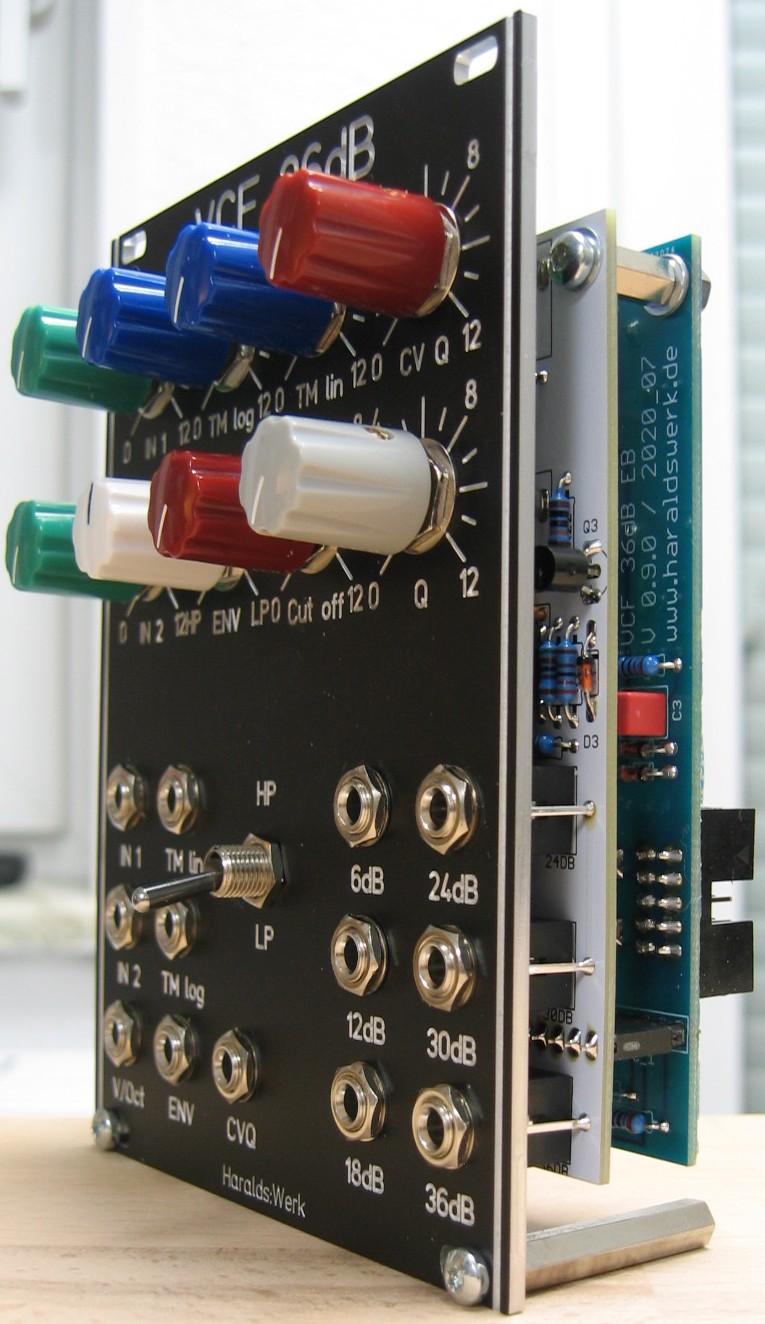
VCF 36dB: Front view
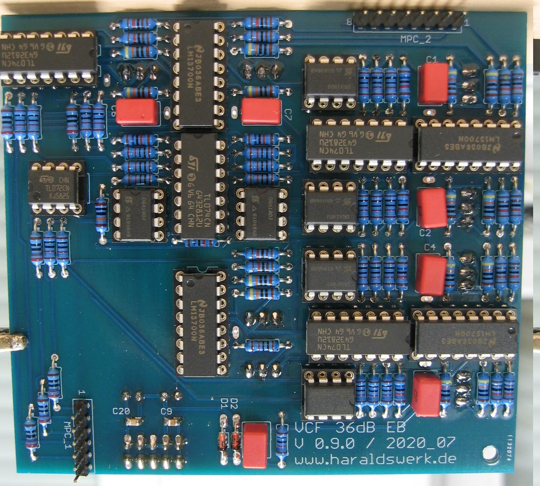
VCF 36dB: Populated control PCB
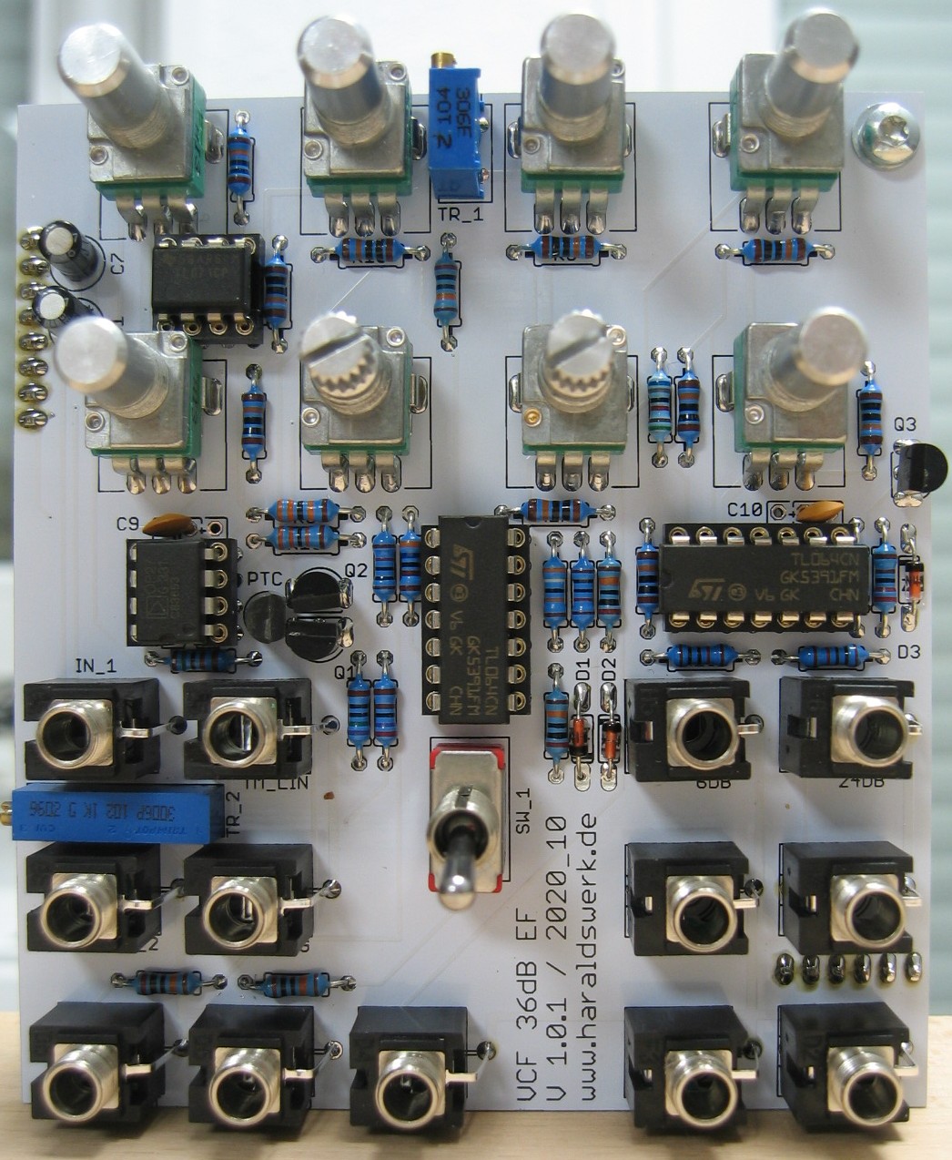
VCF 36dB: Populated main PCB
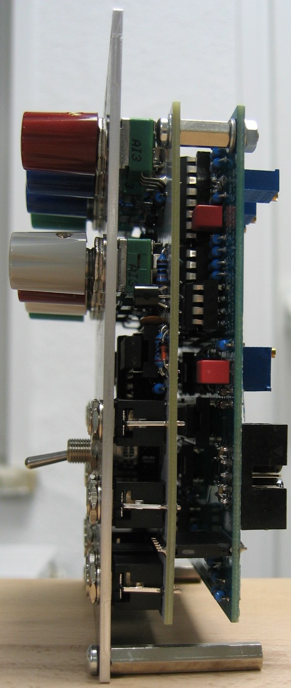
VCF 36dB: Side view